


MASTER HE
SPTMHEE3T16FREN
18
9.
COMMUNICATION
The alarms, commands and the communication software supplied together with the UPS to interface the unit with the
system are listed below.
If these are not sufficient, please see the Options chapter.
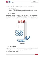
Two DB9 connectors are available for RS232 connection; these outputs can be connect to a remote computer or to a
Modem.
Interface card with connectors for signals and remote commands
9.1.
Report Signals
These are provided by means of voltage-free relay contacts (the maximum capacity of the contacts is: 1 A – 42 V):
•
Battery low;
•
Battery discharged;
•
Load on by-pass or UPS fault.
9.2.
Commands
The following commands in the UPS can be activated by means of an external voltage at + 12 V 80 mA (max):
•
ON/OFF Inverter (Such alarm can be modified as listed on pages 28-29);
•
Complete shutdown of the UPS.
This signals reporting can be set.
9.3.
Emergency Power Off (E.P.O.)
In the event of an emergency the UPS can be completely shut down by an external command.
A-PARALLEL (optional)
H- REMOTE ALARMS (optional)
B- EPO (emergency power off)
I- REMOTE ALARMS (optional)
C- REMOTE
L- MODEM (optional)
D- RS232-1
M-battery temperature sensor (optional)
E- RS232-2
N- UGS (optional)
F- SLOT 1 (main)
O- 230V-auxilliary outlet
G- SLOT 2 (aux)
P- SWOUT aux
Q- SWMB aux