background image

APPLICATION AND OPERATION (CONTINUED) 

3.   To verify pump is operating correctly.

a.  Disconnect pump from power source.
b.  Connect hose adapter and discharge hose to pump.
c.  Immerse pump in a bucket or tub of water at least 1-3/4 

inches in depth.

d.  Place the other end of the discharge hose outside the 

bucket, so the water will pump out.

e.  Plug power cord into a grounded 120 volt GFCI power 

outlet. The pump should start after 2 seconds of 
detecting water. Once the pump removes the water to a 
depth of 3/8 inch, the pump will stop automatically. 

f.  If pump does NOT operate, unplug power cord and 

proceed to maintenance – step 5.

4.   To verify discharge hose is free from a blockage.

a.  Connect hose to another water source such as a faucet. 

If water flows through hose, return to step 3a. If water is 
restricted, verify discharge hose is unwound. Remove all 
kinks, bends, or obstructions in hose.

b.   If pump is still NOT operating, proceed to step 6.

5.   Periodic cleaning of pump is required to maintain 

performance of the pump. Follow the cleaning steps listed 
below: 
a.  Unplug the power cord.
b.  Remove the four (4) base screws (Figure 2).
c.  Remove the base and impeller plate.
d.  Remove the debris and make sure the impeller turns 

freely.

e.  Reinstall impeller plate, base, and screws.

6.  Check the priming hole for obstruction. (Figure 2). 

Follow the cleaning steps listed below:

a.  Unplug the power cord.
b.  Remove the four (4) base screws (Figure 2).
c.  Remove the base and impeller plate.
d.  Use a pin or paperclip to clean the priming hole and air 

escape channel.

e.  Reinstall impeller plate, base and screws.

3.   For best pump performance, unwind the hose before starting 

the pump. This will help remove any kinks or binds in the 
hose and allow the unit to pump with less restriction.

4.   Set the pump on a hard, flat surface in the water. Do not set 

the pump directly on mud or sand surfaces. This will cause 
the inlet screen to clog. 

5.   The water level must be at least 1-3/4 inches for the pump 

to cycle, prime, and operate. Water levels less than 1-3/4 
inches will not allow the impeller to contact water therefore 
no water will be pumped.

 Do 

NOT handle pump with wet       

  hands or when standing in water 

or on a damp surface when the unit is operating or fails to 

operate. ALWAYS disconnect pump power cord from 

power source before handling.

6.   Plug the pump into a 120 volt GFCI protected outlet. The 

pump will start automatically when the water reaches a depth 
of 1-3/4 inches. A priming delay of 2 seconds is programmed 
into the control to allow time for air to escape from the 
pumping chamber. 

7.   The pump will stop automatically once water has been 

removed to a depth of approximately 3/8 of an inch above 
the hard surface. The pump will not restart until the water 
depth rises to 1-3/4 inches or greater.

8.   The pump will not allow itself to run dry. Once the pump 

detects that water is no longer being removed, it will shut down 
automatically. The pump must remain upright at all times in 
order for the water detection to function. The shaft seal depends 
on water for lubrication. Do not allow the pump to operate on its 
side or inverted.


Do NOT alter the pump to override the automatic

  water detector. The shaft seal depends on water 

for lubrication. Overriding this pump feature can cause the pump to run 

dry and may damage the shaft seal and cause pump failure.

MAINTENANCE AND TROUBLESHOOTING


Pump starts automatically.            

  Always disconnect electric supply 

before attempting to install, service, relocate, or 

perform any maintenance. Failure to do so could result 

in fatal electrical shock.

Minimal service is required for this pump. The motor housing of 

the pump is completely sealed and requires no service. If pump 

should fail to operate, perform the following troubleshooting 

guidelines: 
1.   Verify pumping height does NOT exceed 13 feet (See Figure 

1). If pumping height is greater than 13 feet, this pump will 
NOT operate.

2.   Verify water depth is 1-3/4 inches or greater (See Figure 1).


Do NOT disassemble or alter this  

  product in any way. Failure to 

follow these instructions will result in serious injury or 

death.

13 FT MAXIMUM 

PUMPING HEIGHT

Figure 1 - Pumping Height

WATER LEVEL MINIMUM: 
1-3/4 INCHES

Ridge Tool Company

XXXXX, XXXXX and XXXXX

Models RUA25, RAPC250 – Operating Instructions and Parts Manual

3

Содержание RAPC250

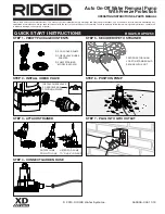
Страница 1: ... TO LOCK LISTEN FOR PUMP TO CLICK IN PLACE FEED ROPE THROUGH LOOP ON STRAINER AND SECURE WITH KNOT CLICK TOP INSTALL CHECK VALVE SO ARROWS ARE POINTING UPWARD STEP 1 VERIFY PACKAGE CONTENTS Please read and save these instructions This manual contains important Safety Warnings and Operating Instructions You will need to refer to it before attempting any application or maintenance Always keep this m...

Страница 2: ...ve locations 1 This pump has been designed with 1 1 4 in NPT discharge connection size Attach pipe or fitting to the discharge or use the supplied garden hose adapter Thread the female end of the garden hose to the male end of the elbow 2 Be certain to use a hose washer not included on the garden hose for correct pump operation DESCRIPTION This portable submersible utility pump is designed for aut...

Страница 3: ...w the impeller to contact water therefore no water will be pumped Do NOT handle pump with wet hands or when standing in water or on a damp surface when the unit is operating or fails to operate ALWAYS disconnect pump power cord from power source before handling 6 Plug the pump into a 120 volt GFCI protected outlet The pump will start automatically when the water reaches a depth of 1 3 4 inches A p...

Страница 4: ...on page 3 Pump will not shut off or runs continuously 1 Debris in switch 2 Discharge height exceeds capability 1 Rinse out switch with clean water Figure 3 on page 3 2 Raise pump or reduce discharge height Pump operates but delivers little or no water 1 Impeller obstructed 2 Priming hole plugged 3 Obstructed piping 4 Discharge height exceeds capability 1 Remove base and impeller plate Figure 2 on ...

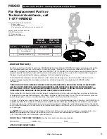
Страница 5: ...pecific legal rights and you may also have other legal rights which vary from state to state In no event whether as a result of breach of contract warranty tort in clud ing negligence or otherwise shall RIDGID or its suppliers be liable for any special consequential incidental or penal damages including but not limited to loss of profit or revenues loss of use of the products or any associated equ...

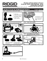
Страница 6: ...U FILTRE ÉTAPE 6 POMPE POSITIONNEMENT ÉTAPE 7 BRANCHEMENT DANS UNE PRISE À DISJONCTEUR DE FUITE À LA TERRE 1 CLAPET DE NON RETOUR ADAPTATEUR DE TUYAU FAIRE PIVOTER LA POMPE VERS LE BAS POUR LA VERROUILLER UN CLIC SE FERA ENTENDRE LORSQUE LA POMPE SERA BIEN EN PLACE FAIRE PASSER LA CORDE PAR LA BOUCLE SITUÉE SUR LE FILTRE PUIS LA FIXER EN FAISANT UN NŒUD CLIC TOP INSTALLER LE CLAPET DE NON RETOUR E...

Страница 7: ...enceintes souterraines pour pomper les effluents ou les eaux usées NE JAMAIS utiliser dans des endroits dangereux ou explosifs 1 Cette pompe a été conçue avec une taille de décharge de 1 1 4 po NPT Connecter le tuyau ou le raccord à la décharge ou utiliser l adaptateur de tuyau d arrosage fourni Enfiler l extrémité femelle du tuyau d arrosage à l extrémité mâle du coude 2 S assurer d utiliser une ...

Страница 8: ...teur de pompage NE dépasse PAS 4 m 13 pi voir la Figure 1 Si la hauteur de pompage dépasse 4 m 13 pi cette pompe NE fonctionnera PAS 2 Vérifier que la profondeur de la pompe est de 4 4 cm 1 3 4 po ou plus voir la Figure 1 NE PAS démonter ou modifier ce produit de quelque manière que ce soit Ne pas suivre cet avertissement peut mener à de graves blessures ou à la mort 3 Pour vérifier si la pompe fo...

Страница 9: ...émarre et s arrête trop souvent 1 Retour d eau de tuyauterie 2 Interrupteur sale 3 Trou d amorçage bouché 1 Installer ou remplacer le clapet de non retour vendu séparément 62061 001 2 Rincer l interrupteur à l eau propre Figure 3 3 Nettoyer le trou l intérieur du boîtier de volute avec une épingle ou un trombone Figure 2 La pompe ne s arrête pas ou fonctionne continuellement 1 Débris dans l interr...

Страница 10: ...uvez avoir d autres droits légaux qui varient d une juridiction à l autre En aucun cas soit par suite d une rupture de contrat de garantie acte dommageable y compris la négligence ou autre ni RIDGID ni ses fournisseurs ne seront responsables de tout dommage spécial consécutif indirect ou punitif y compris mais sans s y limiter à la perte de profits ou recettes la perte d usage des produits ou de t...

Страница 11: ...FILTRO DE LA BOMBA MODELO RAPC250 PASO 2 INSTALE LA VÁLVULA DE RETENCIÓN PASO 3 ACOPLE EL FILTRO PASO 4 CONECTE LA MANGUERA DE JARDÍN PASO 5 SUJETE LA CUERDA AL FILTRO PASO 6 COLOQUE LA BOMBA PASO 7 ENCHUFE EN UN TOMACORRIENTE GFCI 1 VÁLVULA DE RETENCIÓN ADAPTADOR DE MANGUERA GIRE LA BOMBA HACIA ABAJO PARA TRABAR ESCUCHE QUE LA BOMBA HAGA CLIC Y SE FIJE EN POSICIÓN PASE LA CUERDA POR EL PESTILLO D...

Страница 12: ...aves o la muerte Esta unidad NO está diseñada para uso bomba de sumidero o en aplicaciones de sumiderocomo Esta unidad NO está diseñada para usar en tanques sépticos ni sótanos subterráneos para bombear aguas residuales o efluentes NUNCA la utilice en ubicaciones peligrosas u explosivas 1 Esta bomba fue diseñada con un tamaño de conexión de descarga de 1 1 4 pulg NPT Conecte la tubería o la conexi...

Страница 13: ... y plana en el agua No coloque la bomba directamente sobre una superficie lodosa o arenosa Esto obstruirá el filtro de entrada 5 El nivel del agua debe ser de al menos 4 4 cm 1 3 4 pulg para que la bomba se pueda hacer funcionar en ciclos cebar y funcionar Los niveles de agua inferiores a 4 4 cm 1 3 4 pulg no permitirán que el impulsor entre en contacto con el agua en consecuencia no se bombeará a...

Страница 14: ...a capacidad 1 Enjuague el interruptor con agua limpia Figura 3 2 Eleve la bomba o reduzca la altura de descarga La bomba funciona pero sale muy poca agua o nada 1 Impulsor obstruido 2 Orificio de cebado obstruido 3 Tubería obstruida 4 La altura de descarga excede la capacidad 1 Quite la base y la placa del impulsor Figura 2 verifique que no tengan residuos limpie 2 Limpie el orificio dentro de la ...

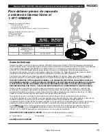
Страница 15: ...OPÓSITO EN PARTICULAR ESTÁN LIMITADAS A UN AÑO A PARTIR DE LA FECHA DE COMPRA ESTE ES EL RECURSO EXCLUSIVO Y SE EXCLUYE CUALQUIER RESPONSABILIDAD POR TODO Y CUALQUIER DAÑO INDIRECTO O CONSECUENTE O GASTOS AFINES Ciertos estados no permiten limitaciones sobre el período de duración de las garantías implícitas ni permiten las exclusiones ni limitaciones de los daños incidentales o consecuentes de fo...

Страница 16: ...Notes Remarques Notas Ridge Tool Company 16 Ridge Tool Company Modelos RUA25 RAPC250 Manual de instrucciones de funcionamiento y piezas de repuesto ...

Отзывы: