background image

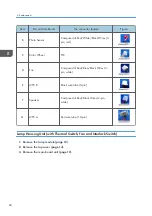
Item

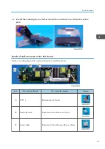
Port on Main Board

The connector feature

Figure

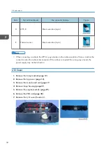
D

LVPS B

Black wire tube (4-pin)

E

Thermal sensor

Black wire tube (5-pin)

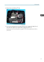
• When connecting a cable to the LVPS A, pay attention to the cable orientation. Place a mark on the

connector when the cable is disconnected. If the cable is connected the wrong way around, the
power supply may not be turned on.

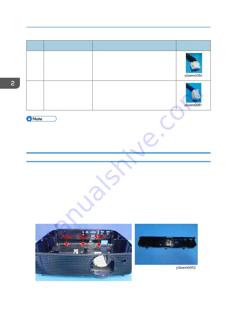
I/O Cover

1.

Remove the lamp module (

page 12

).

2.

Remove the top cover (

page 14

).

3.

Remove the main board unit (

page 19

4.

Remove lamp housing (

page 22

5.

Remove the engine module (

page 27

).

6.

Remove the PSU unit (

page 30

).

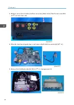
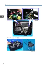
7.

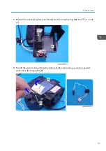
Remove the I/O cover (hook x3).

2. Replacement

34

Содержание Mira-PJ1

Страница 1: ... RICOH PJ S2440 X2440 WX2440 S2650 X2650 KW3680 S2660 S2670 X2670 KW3660 S2680 X2680 S2690 X2690 Machine Codes Y0AF Y0AL Y0AQ Y0AG Y0AM Y0AR Y0AH Y0AJ Y0AN Y0B3 Y0AK Y0AP Y0B1 Y0B2 Field Service Manual Aug 2016 ...

Страница 2: ......

Страница 3: ... melt lead free solder is high Prevention of Physical Injury 1 Before disassembling or assembling parts of the machine and peripherals make sure that the machine power cord is unplugged 2 The wall outlet should be near the machine and easily accessible 3 If any adjustment or operation check has to be made with exterior covers off or open while the main switch is turned on keep hands away from elec...

Страница 4: ... product or used lamps in accordance with local regulations The following information is only for EU member states The use of the symbol indicates that this product may not be treated as household waste By ensuring this product is disposed of correctly you will help prevent potential negative consequences for the environment and human health which could otherwise be caused by inappropriate waste h...

Страница 5: ... Cover with Zoom Lever and Keypad Rubber 14 Speaker 15 IR Sensor 17 Photo Sensor 18 Main Board Unit with RS 232C Connector and Shielding Bracket 19 Details of each connector and FFC on the main board 21 Lamp Housing Unit with Thermal Switch Fan and Interlock Switch 22 Engine module with Color Wheel Modules Focus Ring and Lens 27 PSU with Insulating Sheet and Bottom Shield Plate 30 Details of each ...

Страница 6: ...tment 45 Environment 45 Procedure 45 4 Troubleshooting Main Procedure 47 LED Lighting Message 51 5 Firmware Update System Firmware Update 53 Equipment Needed 53 Software 53 Hardware 53 DLP Composer Lite Setup Procedure 54 Get into Firmware Download Mode 57 Preparation of the projector 57 USB Driver Update Procedure 57 System Firmware Update Procedure 59 4 ...

Страница 7: ...05 x H40 5mm not including focus ring rubber foot protruding parts 3 Weight 2 2Kg 4 Power Supply Universal AC 100 z 240V 50 60 Hz with PFC input 5 Power Consumption Operation mode Bright mode Typ 230W max 253W 110Vac Typ 225W max 248W 220Vac Operation mode ECO mode Typ 190W max 209W 110Vac Typ 187W max 206W 220Vac 6 Keystone correction 40 degree 7 Throw Ratio For PJ S2440 S2650 S2660 S2670 S2680 S...

Страница 8: ...ve dots For PJ S2440 S2650 S2660 S2670 S2680 S2690 800x600 For PJ X2440 X2650 X2670 X2680 X2690 1024x768 For PJ WX2440 WX2440 KW3680 KW3660 1280x800 13 System controller DDP4421 14 Video Compatibility Standards NTSC M J 3 58MHz 4 43 MHz PAL B D G H I M N 4 43 MHz SECAM B D G K K1 L 4 25 4 4 MHz SDTV 480i p 576i p HDTV 720p 50 60Hz 1080i p 50 60Hz 15 Temperature Operating 5 40 C ECO 5 45 C Non oper...

Страница 9: ... C 2500 5000 ft 5 35 C 5000 10000 ft 5 30 C Compatible Mode VGA Analog Analog RGB Compatible Modes Resolution V Frequency Hz VGA 640 x 480 60 VGA 640 x 480 67 VGA 640 x 480 72 VGA 640 x 480 85 SVGA 800 x 600 56 SVGA 800 x 600 60 SVGA 800 x 600 72 SVGA 800 x 600 85 SVGA 800 x 600 120 XGA 1024 x 768 48 XGA 1024 x 768 50 XGA 1024 x 768 60 XGA 1024 x 768 70 XGA 1024 x 768 75 Specifications 7 ...

Страница 10: ...60 WXGA 1280 x 768 75 WXGA 1280 x 768 85 WXGA 1280 x 800 48 WXGA 1280 x 800 50 WXGA 1280 x 800 60 WXGA 1366 x 768 60 SXGA 1280 x 1024 60 SXGA 1280 x 1024 75 SXGA 1280 x 1024 85 SXGA 1400 x 1050 60 UXGA 1600 x 1200 60 HDTV 1080p 1920 x 1080 24 HDTV 1080p 1920 x 1080 50 HDTV 1080p 1920 x 1080 60 WUXGA 1920 x 1200 60 WUXGA 1920 x 1200 50 1 Product Information 8 ...

Страница 11: ...XGA 1024 x 768 60 XGA 1024 x 768 70 XGA 1024 x 768 75 XGA 1024 x 768 85 XGA 1024 x 768 120 SDTV 480I 720 x 480 60 SDTV 480P 720 x 480 60 SDTV 576I 720 x 576 50 SDTV 576P 720 x 576 50 WSVGA 1024 x 600 1024 x 600 60 HDTV 720p 1280 x 720 50 WXGA 1280 x 768 60 WXGA 1280 x 768 75 WXGA 1280 x 768 85 WXGA 1280 x 800 60 WXGA 1280 x 800 120 WXGA 1280 x 800 50 Specifications 9 ...

Страница 12: ...XGA 1400 x 1050 85 SXGA 1400 x 1050 120 UXGA 1600 x 1200 60 HDTV 1080i 1920 x 1080 50 HDTV 1080i 1920 x 1080 60 HDTV 1080p 1920 x 1080 24 HDTV 1080p 1920 x 1080 30 HDTV 1080p 1920 x 1080 50 HDTV 1080p 1920 x 1080 60 WUXGA 1920 x 1200 60 WUXGA 1920 x 1200 50 If the Computer Compatibility supportive signal is different from User s Manual please refer to User s Manual 1 Product Information 10 ...

Страница 13: ...2 Replacement Equipment Needed 1 Screw Driver 105 2 Screw Driver 107 3 Screw Driver 107 4 Hex Sleeves 5mm 5 Tweezers 6 Long nosed Pliers 7 Projector 11 ...

Страница 14: ...rd you have to get into service mode and record the LED usage hours page 43 Re write Lamp Hours Usage Lamp Cover and Lamp Module 1 Loosen a screw on the left side of the unit M3 x8 5 x1 2 Slide and remove the lamp cover A If the lamp cover is difficult to slide insert a flathead precision screwdriver into the gap to slide the cover 2 Replacement 12 ...

Страница 15: ...3 Loosen a screw on the lamp module A M3 5 x8 5 x1 4 Disconnect the plug A x1 Part Replacement 13 ...

Страница 16: ...5 Remove the lamp module A Top Cover with Zoom Lever and Keypad Rubber 1 Remove screws from the bottom cover M3 x8 x 6 2 Replacement 14 ...

Страница 17: ...2 Remove the top cover A hook x10 3 Place the top cover upside down and remove the zoom lever A and keypad rubber B M3 x6 x1 Speaker 1 Remove the top cover page 14 Part Replacement 15 ...

Страница 18: ...2 Disconnect the connector A from the main board 3 Remove the speaker A 2 Replacement 16 ...

Страница 19: ...4 Remove the speaker rubber A IR Sensor 1 Remove the top cover page 14 2 Disconnect the connector A from the main board Part Replacement 17 ...

Страница 20: ...3 Remove the IR sensor A M2 6 x 6 x1 Photo Sensor 1 Remove the top cover page 14 2 Disconnect the connector A from the main board 2 Replacement 18 ...

Страница 21: ...he photo sensor A M2 6 x6 x1 Main Board Unit with RS 232C Connector and Shielding Bracket 1 Remove the top cover page 14 2 Remove screws and disconnect connectors and FFC M2 6 x6 x4 x6 FFC x1 Part Replacement 19 ...

Страница 22: ...cles and hex screws as yellow circles from the rear cover M3 x5 x2 hex screws x4 4 Place the main board upside down and remove the RS 232C connector A x1 5 Remove the shielding bracket A M3 x5 x1 hexagon post x1 2 Replacement 20 ...

Страница 23: ...ails of each connector and FFC on the main board Make sure cables plug into the correct ports when assembling the unit Item Port on Main Board The connector feature Figure A IR Sensor Composed of Red White Black Wires 3 pin white Part Replacement 21 ...

Страница 24: ... Composed of Red Blue Black Wires 3 pin white E LVPS B Black wire tube 5 pin F Speaker Composed of Red Black Wires 2 pin white G LVPS A Red wire tube 10 pin Lamp Housing Unit with Thermal Switch Fan and Interlock Switch 1 Remove the lamp module page 12 2 Remove the top cover page 14 3 Remove the main board unit page 19 2 Replacement 22 ...

Страница 25: ...ulating sheet on the PSU disconnect the connectors A B C and then pull out the cables to the outside of the insulating sheet x3 For how to turn over the insulating sheet see page 30 PSU with Insulating Sheet and Bottom Shield Plate Part Replacement 23 ...

Страница 26: ...6 Remove the lamp housing A 2 Replacement 24 ...

Страница 27: ...ase the connector for lamp module A from the lamp housing M2 6 x7 x1 hook x1 8 Peel off the aluminum tape A on the bottom of the lamp housing as much as needed and remove the lamp cable B Part Replacement 25 ...

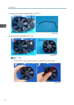
Страница 28: ...9 Remove the thermal switch A M2 6 x7 x1 10 Remove the fan A M3 x10 x4 Hold the frame of the fan A Holding the fan shaft B may cause a failure 2 Replacement 26 ...

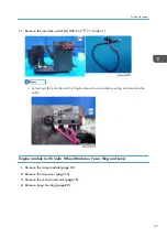
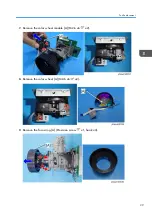
Страница 29: ...witch is fragile take extra care when mounting and removing the switch Engine module with Color Wheel Modules Focus Ring and Lens 1 Remove the lamp module page 12 2 Remove the top cover page 14 3 Remove the main board unit page 19 4 Remove lamp housing page 22 Part Replacement 27 ...

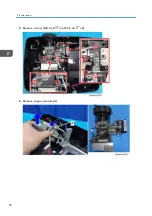
Страница 30: ...5 Remove screws M2 6 x8 x4 M2 6 x6 x2 6 Remove engine module A 2 Replacement 28 ...

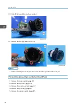
Страница 31: ...7 Remove the color wheel module A M2 6 x6 x2 8 Remove the color wheel A M2 6 x6 x2 9 Remove the focus ring A Precision screw x1 hook x3 Part Replacement 29 ...

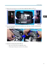
Страница 32: ...e new engine remove dust from the engine base with an air gun PSU with Insulating Sheet and Bottom Shield Plate 1 Remove the lamp module page 12 2 Remove the top cover page 14 3 Remove the main board unit page 19 4 Remove lamp housing page 22 5 Remove the engine module page 27 2 Replacement 30 ...

Страница 33: ... 7 Turn over the tape A that fixes the bottom cover and remove the PSU unit B with the bottom shield plate 8 Open the insulating sheet of the PSU unit Red square These parts are engaged by notches Yellow square These parts are stuck with an adhesive Part Replacement 31 ...

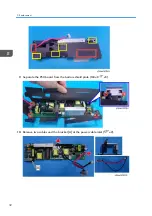
Страница 34: ...9 Separate the PSU board from the bottom shield plate M3 x8 x5 10 Remove two cables and the bracket A at the power cable inlet x2 2 Replacement 32 ...

Страница 35: ...each connector on the PSU board Make sure cables plug into the correct ports when assembling the unit Item Port on Main Board The connector feature Figure A LVPS A Red wire tube 10 pin B Interlock switch Composed of 2 black wires 2 pin C Lamp cable Composed of 2 white wires 2 pin white Part Replacement 33 ...

Страница 36: ... Place a mark on the connector when the cable is disconnected If the cable is connected the wrong way around the power supply may not be turned on I O Cover 1 Remove the lamp module page 12 2 Remove the top cover page 14 3 Remove the main board unit page 19 4 Remove lamp housing page 22 5 Remove the engine module page 27 6 Remove the PSU unit page 30 7 Remove the I O cover hook x3 2 Replacement 34...

Страница 37: ...Adjustable Feet 1 Remove the adjustable feet Part Replacement 35 ...

Страница 38: ...2 Replacement 36 ...

Страница 39: ...Download and Fan RPM Calibration Fan RPM Calibration ADC Calibration page 40 ADC Calibration Version Update page 42 Test Inspection Procedure OSD Reset Reset Lamp Hours page 43 Re write Lamp Hours Usage Rod Adjustment page 45 Rod Adjustment This action is not always required Perform it only if the situation demands it After parts replacement or repair check that the projector works properly Projec...

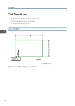
Страница 40: ...ditions Environmental brightness Dark room less than 2 lux Product must be warmed up for 3 minutes Screen size 60 inches diagonal Zone Definition Figure Zone A and Frame as green line Definition 3 Adjustment 38 ...

Страница 41: ... cord 2 Release the power button when the power LED is flashing red 3 After several minutes the projector will auto power on and the fan RPM calibration and auto waveform is finished If the factory fan value doesn t show in service mode please repeat steps 1 to 2 again Make sure the Blower Factory RPM is in the range from 2100 to 2600 Waveform Download and Fan RPM Calibration 39 ...

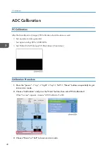
Страница 42: ...0 x 600 60Hz Test Pattern 94 White up 6 Black down See below Calibration Procedure 1 Press the power up right up left Menu buttons sequentially to get into service mode 2 Choose Calibration and press the Enter button then select PC Calibration When Success appears it means ADC Calibration is OK 3 Choose Menu or Exit to leave service mode 3 Adjustment 40 ...

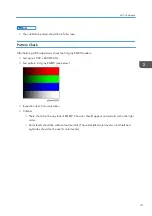
Страница 43: ... x 600 60Hz Test pattern 64 gray RGBW see below Inspection item Color saturation Criteria There should not be any lack of RGBW The color should appear normal and sort in the right order Color levels should be sufficient and normal The unidentified color levels on both left and right sides should not be over 8 color levels ADC Calibration 41 ...

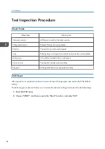
Страница 44: ...able Lamp cover It should be locked in the correct place Zoom in out The function should work smoothly Keypad All keypad buttons must operate smoothly OSD Reset After inspection is completed we have to erase all saved change again and restore the OSD default setting The following procedures will allow you to erase all end users settings and restore the default settings 1 Enter the OSD menu 2 Choos...

Страница 45: ... Right key increases lamp hours 3 Re write Lamp Hours Normal Select Lamp Hours Bright and use the left or right keys to re write the lamp hours Normal 4 Re write Lamp Hours ECO Select Lamp Hours ECO and use the left or right keys to re write the lamp hours ECO 5 Re write Lamp Hours Dynamic Select Lamp Hours Dynamic and use the left or right keys to re write the lamp hours Dynamic 6 Re write Lamp H...

Страница 46: ...7 Choose Exit and then press Enter to exit 3 Adjustment 44 ...

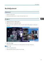
Страница 47: ...creen 2 Adjust the screws to readjust the image Screw A should be adjusted first and then screw B Adjust until the yellowish or bluish parts disappear 3 Inspect the image There should not be no abnormal color within the frame of the image visible by eye Avoid over adjusting the rod After adjustment is finished fix these screws with glue Rod Adjustment 45 ...

Страница 48: ...3 Adjustment 46 ...

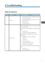
Страница 49: ...t the projector is not put on a soft pad and the air vent is not blocked a Lamp failed Power LED flashes red Lamp LED lights red Check the Lamp Check the LVPS Check the Main Board b Fan failed Power LED flashes red Temp LED flashes red Check whether you have executed Fan Calibration Check the Fan Check the Main Board Check the Color Wheel Module Check the Photo Sensor Board c Over Temp Power LED f...

Страница 50: ...time use the Source button switch Ensure that all connectors are securely connected and aren t broken Check the Main Board Check the DMD Chip Check the Color Wheel Check the Engine Module 5 Mechanical Noise Check the Color Wheel Check the Fan Module 6 Line Bar Line Defect Check the Main Board Check the DMD Chip 7 Image Flicker Do Reset All data in the OSD Menu Ensure that the signal cables and sou...

Страница 51: ...sure that the projection lens is clean Clean the DMD Chip and the Engine Module Check the DMD Board Check the Engine Module 11 Garbled Image Ensure that the signal cables and source work Check the Main Board 12 Remote Controller Failed Remote Controller a Check the Battery b Check the Remote Controller c Check the IR Sensor Board d Check the Main Board 13 Function Abnormal Do Reset All data in the...

Страница 52: ...re that the 3D glasses are good and that the user is facing the projection correctly Ensure that the signal source is in 3D format Ensure that the 3D function of the projector OSD is on and 3D sync invert is on Check Main Board 4 Troubleshooting 50 ...

Страница 53: ...Green Red Red Standby State Input power cord Steady light Off Off Off Power on Warming Off Flashing Off Off Lamp lighting Off Steady light Off Off Power off Cooling Off Flashing Off Off Error Lamp Fail Flashing Off Steady light Off Error Fan Fail Flashing Off Off Flashing LED Lighting Message 51 ...

Страница 54: ...Message Power LED Lamp LED Temp LED Red Green Red Red Error Over Temp Flashing Off Off Steady light 4 Troubleshooting 52 ...

Страница 55: ...5 Firmware Update System Firmware Update Equipment Needed Software 1 DLP Composer Lite 11 2 2 Firmware img 3 FlashDeviceParameters 20141125 Hardware 1 Projector 2 Power Cord 3 USB Cable A to B 4 PC 53 ...

Страница 56: ...Procedure 1 Start the DLP Composer Lite V11 2 Setup Program 2 Click Next 3 Read License Agreement Choose I accept and agree to be bound by all the terms and conditions of this License Agreement Click Next 5 Firmware Update 54 ...

Страница 57: ...4 Click Next 5 Click Next System Firmware Update 55 ...

Страница 58: ...6 Click Next 7 The program is in installing status 8 Click Finish 5 Firmware Update 56 ...

Страница 59: ...ld down the power key then plug in the power cord 2 After three LEDs are lit red release the power button 3 Connect the projector to the PC with the USB cable USB Driver Update Procedure 1 Execute Install DLP Device Drivers in the start menu System Firmware Update 57 ...

Страница 60: ...2 Select Jungo WinDriver WinXP then click install 3 Click Next 5 Firmware Update 58 ...

Страница 61: ...e Procedure 1 Execute the DLP ComposerTM Lite 11 2 file 2 Set the FlashDeviceParameters Select the file FlashDeviceParameters Put FlashDeviceParameters file into the folder where you setup DLP Composer Lite 11 2 System Firmware Update 59 ...

Страница 62: ...3 Select Edit Preferences 4 Click Communications to open the Communications setting dialog 1 Select USB 2 Click OK 5 Firmware Update 60 ...

Страница 63: ...5 Choose Flash Loader 1 Click Browse to search for the firmware file img 2 Select the firmware file img and then click Open System Firmware Update 61 ...

Страница 64: ...6 Select the item skip Boot Loader Area 1 Select 32KB 2 Click Reset Bus to erase the flash memory 5 Firmware Update 62 ...

Страница 65: ...7 If the firmware is ready click Start Download to execute the firmware update Click Yes to erase the flash memory System Firmware Update 63 ...

Страница 66: ... When finished Download completed will appear on the screen Unplug the USB cable and power cord 9 Check the System firmware version Plug the power cable in again then restart the unit and get into the Service Mode to check the system firmware version 5 Firmware Update 64 ...

Страница 67: ...System Firmware Update 65 ...

Страница 68: ...MEMO 66 ...

Страница 69: ...MEMO 67 ...

Страница 70: ...MEMO 68 EN ...

Отзывы: