


DRUM
1 July, 1998
2-50
2.5.6 MASTER DETECTION
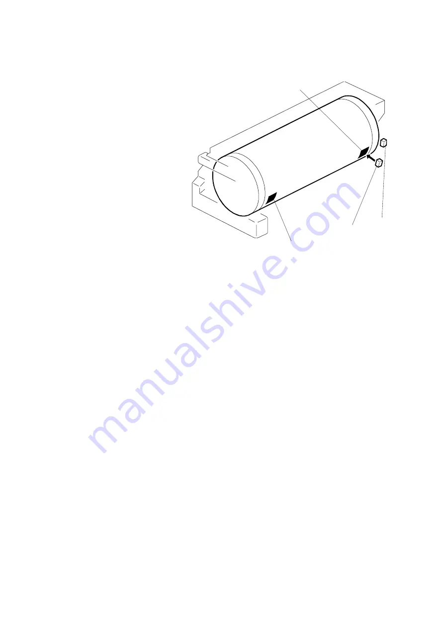
The 1st drum master sensor
[A] detects a master on the
drum.
If a master is on the drum, the
black patch [B] is covered and
the sensor detects the light
reflected from the master.
Printing starts when the start
key is pressed. If an original
has been set, the master is
ejected before making a new
master.
If no master is on the drum, the
black patch is exposed. The
black patch does not reflect
light back to the sensor. The
machine will skip the master eject process and immediately begin making a new
master.
A similar sensor, the 2nd drum master sensor [C], is located just above the 1st
drum master sensor. This sensor determines if the master making process
correctly wrapped the master around the drum.
The drum starts turning soon after the drum master clamper clamps the leading
edge of the master. The 2nd drum master sensor checks for the presence of the
master (master clamping error check). If a master is not detected, a clamping error
occurred. The master feed stops, the drum returns to the home position, and the
machine displays a master feed jam message.
The 1st drum master sensor cannot check for master clamping errors, because the
black patch has moved.
Both sensors use the same black patch [A] to detect the master.
NOTE: There are two black patches on the drum screen. Patch [D] does not face
the drum master sensors and is not used for master detection.
The surface of the patches is slightly higher than the surface of the rest of
the drum screen. The extra patch ensures that the master pick-up roller
contacts the drum surface evenly at this part of the drum, resulting in even
pressure from the roller all across the drum.
C229D019.WMF
[A]
[B]
[C]
[D]
Содержание Gestetner 5450
Страница 1: ...SERVICE MANUAL Machine code C229...
Страница 11: ...MACHINE INTERIOR 1 July 1998 1 6 1 3 MACHINE INTERIOR C229V501 WMF...
Страница 193: ...EXTERIOR 1 July 1998 6 2 6 1 2 REAR AND LEFT COVERS A Rear cover B Left cover C229R512 WMF A B...
Страница 195: ...EXTERIOR 1 July 1998 6 4 6 1 4 INNER COVER AND KNOB COVER A Inner cover B Knob cover C229R511 WMF A B...
Страница 220: ...1 July 1998 MASTER FEED SECTION 6 29 Replacement Adjustment D Duct entrance solenoid C229R064 WMF D...
Страница 304: ...1 July 1998 7 2 Location Map C229S500 WMF...
Страница 305: ...1 July 1998 7 3 P to P Section A C229S501 WMF...
Страница 306: ...1 July 1998 7 4 Section B C229S502 WMF...
Страница 307: ...1 July 1998 7 5 P to P Section C C229S503 WMF...
Страница 308: ...1 July 1998 7 6 Section D C229S504 WMF...
Страница 309: ...1 July 1998 7 7 P to P Section E C229S505 WMF...
Страница 310: ...1 July 1998 7 8 Section F C229S506 WMF...