background image

Install Conduit, Cabling, and J-Boxes

21

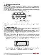
 Figure 8-6. Trimming Load Cell Numbers Two, Three, and Four

3. The lowest reading of the four will be your reference cell. You won’t change that cell’s signal. Instead

you’ll use the individual cell potentiometers for the other three cells to reduce those signals to match your
reference cell. Remember that you turned all pots to full signal (0 resistance) before starting. So you can’t
increase the signal from any cell—you can only decrease signal by trimming with the pots.

4. Note that the best trim is always the least trim. If one of the four readings differs from the others by more

than 5% of the displayed counts, there is probably a mechanical problem with that load cell mount causing
the large difference. Find it and correct it before going on. Check for binding, an out-of-level or misaligned
link, or similar problems with the load cell and mount. 

Do not

 try to trim down large signal differences

with resistance pots—you’ll only add larger problems for yourself later because of interaction between
mounts.

5. Park the loaded weight cart over one of the high-reading cells on Side 1. Turn that cell’s individual

potentiometer until the displayed reading equals your recorded reference cell reading. Repeat for the other
two high-reading cells on side 1.

6. As adjustments are somewhat interactive, repeat the process in Steps 1 through 5 until all four cells on Side

1 read within 1% of each other.

7.

Side 2.

 Move to the Side 2 of the scale. Load each cell in turn with the weight cart and record readings on

those four cells in the same way. 

The cell which 

reads the closest to the Side 1 reference cell

 will be

used as your reference cell for trimming the other cells on side 2.

 Figure 8-7. Trimming Load Cell Number Five

The reference cell on Side 2 should be the same as the Side 1 readings. Move the weight cart over the cell
chosen for the Side 2 reference cell. Adjust the cell’s individual pot to equal the final Side 1 readings. In the
example at left, Cell 8 has been chosen as the Side 2 reference cell

8. Reload the other Side 2 cells (5, 6, 7 in the example) in turn with the weight cart and adjust their individual

pots so their readings are equal to the Side 2 reference cell (8 in the example).

Figure 8-8. Trimming Load Cell Number Eight

9. Repeat Steps 7 through 9 if needed to get all Side 2 cells reading within 1% of each other and within 1% of

the Side 1 reference cell.

1

4

3

2

8

5

6

7

1

4

3

2

8

5

6

7

Note

1

4

3

2

8

5

6

7

Содержание Survivor SR

Страница 1: ...SURVIVOR SR Siderail Truck Scale Assembly Instructions 45698 Rev D...

Страница 2: ......

Страница 3: ...olt Tightly 7 3 1 Align and Square Deck 7 3 2 Level Frame 7 4 0 Set Load Cell Mounts 8 4 1 Attach Mount Chair 8 4 2 Prepare Baseplate and Load Cell 8 4 3 Set Baseplate 8 4 4 Raise Link and Load Cell 8...

Страница 4: ...le Assembly Instructions Rice Lake continually offers web based video training on a growing selection of product related topics at no cost Visit www ricelake com webinars 9 0 Vehicle Scale Limited War...

Страница 5: ...s situation that if not avoided could result in serious injury or death and includes hazards that are exposed when guards are removed Indicates a potentially hazardous situation that if not avoided ma...

Страница 6: ...m strength may damage the foundation 1 2 2 Delivery Crane Rental and Assembly Estimates When scheduling scale delivery and crane forklift rental for the unloading and frame placement arrange a full da...

Страница 7: ...string line and squared with the foundation approaches This line of side rail beams becomes the reference line to which the other side rail and all cross beams are aligned Side to Side Assembly Seque...

Страница 8: ...and bolted to the reference side rail move the opposite side rail for the open side into position with the forklift With the cross beams resting on the side rail flange raise the side rail and cross...

Страница 9: ...ositioning The following sections outline the positioning and numbering of the SR truck scale siderail beams 2 2 1 Siderail Positioning Set all side rails with the cut outs for the load cell mount dow...

Страница 10: ...beams hold short support bars over the load cell area to support the corrugated metal there when the deck is poured Position 6 beams so the extra end studs are over the load cell mount Number 7 cross...

Страница 11: ...level of the deck top If adjustments are necessary a fork lift or crane can be used to nudge the frame into alignment 3 2 Level Frame If the concrete foundation pad has been sloped for water drainage...

Страница 12: ...ur leveling screws into the baseplate so about 2 extends beyond the bottom surface as shown at right Each load cell must be fitted with a 90 threaded LB conduit adapter Install an adapter on each load...

Страница 13: ...he chair the link will be hanging exactly vertical when centered in the chair Approximately 1 4 of link should protrude beyond each side of the chair If adjustment is necessary tap baseplate edges lig...

Страница 14: ...holes This long bit allows the drill body to clear the siderail so the hole can be drilled nearly vertical Hold the bit as close to vertical as possible and drill a 3 4 hole at least 6 into the concr...

Страница 15: ...short support bar is installed next to the load cell window as shown at left 6 2 Corrugated Metal Sheeting Lay in 28 gauge 3 4 corrugated galvanized panels 1 1 4 wide corrugations to support the conc...

Страница 16: ...to hold the rebar 1 5 above the corrugated panels Begin laying the rebar gridwork by tying long rebars parallel to the cross beams under the Nelson studs on each cross beam Rebar ties and spinner too...

Страница 17: ...derails a fraction of an inch and rest them on temporary blocks as shown at right This is rarely necessary but may prevent damage from a concrete redi mix truck accidentally backing into the scale fra...

Страница 18: ...the next concrete truck Don t forget to clean out concrete from the drain tubes on each bay For a non skid surface use a stiff bristle broom for a brushed finish when the concrete has set enough for f...

Страница 19: ...aintain NEMA 4 integrity Figure 8 1 J Box Wiring and conduit Runs for a Four Section Three Module Scale Load Cell Cable to Connector Pocket 1 Conduit Pocket 8 Conduit Pockets 1 2 3 4 Conduit runs to J...

Страница 20: ...d SI SI EX EX SHD SEN SEN Indicator J10 Expansion J9 Cable from J Box 2 SI Green SI White EX Red EX Black SEN Yellow SEN Blue Pocket 10 Conduit Module C Module B Module A Module D Pocket 4 Conduit 3 8...

Страница 21: ...ential than the main ground the surge may travel out to the scale ground rod damaging load cells on its way A nearby lightning ground strike may instantly raise the zero potential of a ground rod at t...

Страница 22: ...the buried ground cable from the AC power ground rod A DC transient protection board can be conveniently located within the junction box to help protect load cells from power surges If that option is...

Страница 23: ...R2 R33 JP12 JP2 VR9 JP19 R48 VR7 JP18 R42 R44 R22 R25 R16 R18 VR2 R19 R39 VR10 R35 R37 VR11 R27 R29 R31 R9 R11 R12 R1 R3 R5 VR5 R6 JP5 JMP NEG JMP POS VR8 VR3 VR1 VR12 VR6 J1 VR4 J2 R13 R7 EXPANSION J...

Страница 24: ...tion in the junction box clockwise until a clicking noise is heard when you continue turning This eliminates any initial resistance so all signals are at full strength You re now ready to do individua...

Страница 25: ...t cell s individual potentiometer until the displayed reading equals your recorded reference cell reading Repeat for the other two high reading cells on side 1 6 As adjustments are somewhat interactiv...

Страница 26: ...other corners in turn and record those readings The readings should be within 1 of each other 8 8 Calibration with Test Weights The calibration procedure can only be done after all trimming as describ...

Страница 27: ...nt by RLWS confirms that the non conformity actually exists and was not caused by accident misuse neglect alteration improper installation improper repair or improper testing RLWS shall be the sole ju...

Страница 28: ...nd Mexican Customers 800 321 6703 International 715 234 9171 Immediate Emergency Service For immediate assistance call toll free 1 800 472 6703 Canadian and Mexican customers please call 1 800 321 670...

Страница 29: ......

Страница 30: ...68 USA U S 800 472 6703 Canada Mexico 800 321 6703 International 715 234 9171 Europe 31 0 88 2349171 www ricelake com www ricelake mx www ricelake eu www ricelake co in m ricelake com Rice Lake Weighi...

Отзывы: