background image


AS

Mxxxx Series User’s Manual 


Asia Pacific | EMEA | Americas 


77 


Automatic System Isolation Tests: 

 
This determines whether the System Isolation Tests will be performed automatically. 


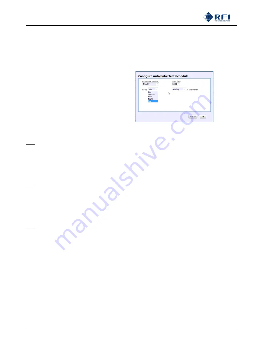
Automatic Test Schedule: 

 
This determines when the 

System Isolation Tests

 will be  

performed when 

Automatic System Isolation Tests

 is selected.   

Clicking 

Edit

 selects a calendar menu that  allows a wide range  

of minute/hour/day/week/month selections to be chosen,  
enabling specific times to be allocated for the System Isolation  
Tests. 


Antenna Isolation Test: 
 
Test Frequency: 

 
The frequency upon which the Antenna Isolation Test will be performed. 
 

Note:

   Depending on local licensing and regulatory requirements this frequency will normally be one of the sites existing  

             Base Station receive frequencies. 


Rx Subsystem Gain(Loss): 


Test Frequency(s): 

 
The frequency(s) upon which the Rx Subsystem Gain/Loss Test will be performed. 
 

Note:

    Depending on local licensing and regulatory requirements this frequency will normally be one of the sites existing  

             Base Station receive frequencies. 


Tx Rejection: 


Test Frequency(s): 

 
The frequency(s) upon which the Tx Rejection Test will be performed. 
 

Note:

    The frequencies selected for this test must be Tx frequencies that are selected in the 

Configuration 

– Tx Ports

 screens. 


Defaults: 

 
Clicking this resets all data fields to the factory defaults. 
 

Discard Changes: 

 
Click this button to restore the values to those current saved.  Note that if invalid values are being displayed after an Apply 
attempt, these values may not match the current system configuration. In this case, just select the 

Configure - Isolation Tests


menu item again to re-display the current configuration. 
 

Apply: 

 
This will attempt to save and activate the values entered. If any out of range values are present, nothing will be saved and the 
problem settings will be highlighted with a red background. 
 

Содержание ASM1317

Страница 1: ...m Monitor ASM1317 ASM3852 ASM7487 ASM8796 Base Line 2 83 Document Number INS40821 3 Australian Standard Patent No 2011218778 Australian Patent Application No 2016250327 U S Patent No 8 983 415 U S Patent Application No 15 343 133 ...

Страница 2: ...ace a quality management program which is certified to ISO9001 environmental management system certification to ISO14001 and occupational health and safety standard AS4801 giving you complete confidence in everything we do RFI s products are truly innovative and as a result we are active around the globe taking our Australian designed and manufactured products to key markets in Asia Pacific the Am...

Страница 3: ...3 2 20 11 th October 2013 2 30 8 th January 2014 2 40 24 th January 2014 2 50 14 th March 2014 2 50b 22 nd April 2014 2 50c 17 th September 2014 2 50d 09 th December 2014 2 50e 11 th March 2015 2 60 15 th July 2015 2 62 19 th January 2016 2 70 15 th March 2016 2 80 30 th January 2017 2 81 27 th April 2017 2 82 03 rd July 2017 2 83 14 th September 2017 ______________________________________________...

Страница 4: ...0 16 History Isolation Tests File 56 10 17 History Rx Power Chart 57 10 18 History Rx Power File 60 10 19 History Tx Power Chart 61 10 20 History Tx Power File 64 10 21 History Alm Mod I P Chart 65 10 22 History Alm Mod I P File 66 10 23 History Alarm Event Log 67 10 24 History Access Event Log 69 10 25 Channel Diagnostics 70 10 26 Configuration Menu 73 10 27 Configuration User Data 74 10 28 Confi...

Страница 5: ...s with Part 15 of the FCC Rules Operation is subject to the following two conditions 1 This device may not cause harmful interference and 2 This device must accept any interference received including interference that may cause undesired operation The user is cautioned that changes and or modifications not approved by the responsible party could void the user s authority to operate the equipment N...

Страница 6: ... reviewed However RF Industries Pty Ltd accepts no liability for any omissions errors or construed information 2011 RF Industries Pty Ltd All rights reserved Reproduction adaptation or translation without prior written permission is prohibited except as allowed under copyright laws For further information or help with this product contact your nearest RFI sales office or through the following Regi...

Страница 7: ...ASMxxxx Series User s Manual Asia Pacific EMEA Americas 7 Antenna System Monitors ASMxxxx Series ASMxxxxK1 Series ASMxxxxK2 Series Front View Rear View Rear View ...

Страница 8: ... User s Manual Asia Pacific EMEA Americas 8 Antenna Line Couplers SP1318 2440 DFF1RU 132 174MHz SP3855 4440 DFF1RU 380 520MHz SP7496 4440 DFF1RU 746 960MHz Top View Front View Top View Front View Front View Top View ...

Страница 9: ...l Modules CAM0000 Series Channel Alarm Module CAM Front Panel Layout Channel Alarm Module CAM Rear Panel Layout SAM0000 Series Site Alarm Module SAM Front Panel Layout Site Alarm Module SAM Rear Panel Layout RSM0000 Series Receive Systems Module RSM Rear Panel Layout ...

Страница 10: ...l web server Access to the GUI is protected by a User Name and Password that is progressively checked for security strength The up to 80 individual Tx and Rx frequencies configured in the ASM are divided across four GUI pages each able to display up to 20 channels each This allows the user to view a large number of channels on a standard monitor screen size without the excessive use of scrolling I...

Страница 11: ...c input level respectively The CAM and the SAM modules provide enhanced monitoring functionality for the ASM allowing a range of PTT temperature voltages and digital inputs to be monitored as part of Antenna Change Over ACO base station hot standby equipment and site monitoring and auxiliary control capabilities Receive Systems Module RSM An optional Receive Systems Module RSM may be fitted to an ...

Страница 12: ...M REAR VIEW ASM 1 ANTENNA LINE COUPLER FWD RFL OPTIONAL DEDICATED Rx MONITORING ANTENNA FROM SPARE PORT S ON BTS Rx MUX S TO ADDITIONAL COUPLERS IF REQUIRED OPTIONAL SAM s or CAM s 1 10 to MONITORED CHANNELS BTS PTT LINE CONDITIONING 10 ASSIGNED ALARM RELAY OUTPUTS 4 EXT ALARM INPUTS 10 EXT ALARM INPUTS OPTIONAL RSM 4 ASSIGNED ALARM RELAY OUTPUTS Rx ANTENNA s Diagram1 ...

Страница 13: ...terface ports K1 hardware variant K2 hardware variant 1 x USB Type B 1 x TCPIP RJ45 Ethernet port on rear 2 x TCP IP RJ45 Ethernet ports on rear Internal alarm relay contacts output connector 1 x DB15 M on rear Visual alarm notification Front panel LED s Configurable alarms Summary Fault Tx FWD min power Tx FWD max power Tx Combiner I L max VSWR max Rx RSSI min level RSSI max level Tx to Rx Antenn...

Страница 14: ...nal temperature range 22 F to 140 F 30 C to 60 C 5 CAM SAM RSM Electrical and Mechanical Specifications CAM Model Number CAM0000 Alarm Outputs 10 Alarm Contact Type Dry Relay N O Common N C Alarm Relay Contact Ratings 50VDC 1A Alarm Inputs 10 configurable one per alarm output 4 configurable general purpose Alarm Input Logic 0 2 5V DC 1 2 5V DC Visual alarm notification Front and Rear panel mounted...

Страница 15: ... 8 pin Phoenix connector 10 x Polarized 3 pin Phoenix connectors 10 x Polarized 2 pin Phoenix connectors 1 x Polarized 2 pin Phoenix connector 1 x DB15 M Mounting 1RU 19 rack mounting Dimensions W 19 x H 1 75 x D 3 W 483 x H 45 x D 77mm Weight 2 2lbs 1kg Operational temperature range 22 F to 140 F 30 C to 60 C RSM Model Number RSM0000 RSM0000 48 Frequency Range 132 960MHz Maximum RF Input Level no...

Страница 16: ... Tx Fwd 4 Tx Rfl 1 Rx Port 9 36VDC ASM7487 48 Antenna System Monitor 746 870MHz 80 Ch 4 Tx Fwd 4 Tx Rfl 1 Rx Port 36 60VDC ASM7487 AC Antenna System Monitor 746 870MHz 80 Ch 4 Tx Fwd 4 Tx Rfl 1 Rx Port 9 36VDC to 90 264V AC external ASM7487 48AC Antenna System Monitor 746 870MHz 80 Ch 4 Tx Fwd 4 Tx Rfl 1 Rx Port 36 60VDC to 90 264V AC external ASM8796 Antenna System Monitor 870 960MHz 80 Ch 4 Tx F...

Страница 17: ... Kit matching connectors for all CAM SAM I O connectors Receive Systems Module Description RSM0000 Receive Systems Module 9 36VDC RSM0000 48 Receive Systems Module 36 60VDC Accessories ASM0000AU AC Plugpack 90 264VAC 12VDC c w 6ft 1 8m Australian IEC Power Cable ASM0000UK AC Plugpack 90 264VAC 12VDC c w 6ft 1 8m UK IEC Power Cable ASM0000US AC Plugpack 90 264VAC 12VDC c w 6ft 1 8m USA IEC Power Ca...

Страница 18: ...ecommended to retain the Factory Test Sheet for future reference An Ethernet jumper cable is included in the packaging provided for your convenience to connect and configure the ASM via an onboard Graphical User Interface GUI from the browser located on your laptop notebook Although the packing box has been designed to provide a significant amount of protection it is important to report any visibl...

Страница 19: ...stribute or transfer the Firmware nor the rights thereof This Firmware License Agreement grants or implies no right title or interest in any intellectual property owned or licensed by RFI Support and Firmware Updates RFI may elect to provide you with customer support and or Firmware upgrades enhancements or modifications for the RFI Firmware at its sole discretion and may terminate such support at...

Страница 20: ... exceeding a calculated coaxial line loss of 3dB The input From Combiner and output To Antenna ports of the Coupler are 7 16DIN F and will require low Inter Modulation IM 7 16DIN M cable connectors to terminate onto the Coupler The use of correct cable cutting and connector preparation tools to terminate the 7 16DIN M connectors is strongly recommended to reduce the possibility of Passive Inter Mo...

Страница 21: ...nated This LED will pulse at regular intervals to indicate comms activity between them and the host ASM Any other illuminated LEDs will be reflecting the current state of the various inputs outputs and alarm states based on the current programmed configuration A CD or USB memory stick is provided with the ASM and contains copies of the QSG Quick Start Guide and ASM User s Manual and other supporti...

Страница 22: ...168 1 200 ASM factory default address Connectivity to the ASM is successful when the following Log In page appears Should the web browser be unable to open this session it may be necessary to set the IP address of your computer to an address in the same IP range i e 192 168 1 180 This is done for example in Windows XP in the following manner 1 Select Start from status menu 2 Single click Control P...

Страница 23: ...configuration settings and alarm threshold parameters as well as the IP address parameters To do this simply switch the ASM off by removing the DC power cable connector Press the factory reset button on the rear of the ASM reconnect the DC power while continuing to hold the reset button down until the green power LED light flashes the Factory reset has started and the reset button may be released ...

Страница 24: ...revent accidental modification or disclosure to unauthorised persons Level 3 User name and password access via the web browser GUI interface facilitates status configure and maintenance screens The unit specific sensitive fields such as Communications Settings SMTP Alarm email account passwords etc are all displayed and available for editing Once the correct User Name and Password is entered the G...

Страница 25: ...ny Group item will navigate you to that item s Status page so that the detail of the alarms can be viewed The following items are displayed Group The group of parameters relevant to each title Tx Antenna Reference The user defined description for the Port Channel Count The number of channels that have been configured for the Port Alarm Status The Fail or OK summary status for the Group Clicking th...

Страница 26: ...ecting each indented topic under Status will display that item as a separate display page Note The Receive Systems Module and Alarm Modules menu items appear only if one or more optional Channel Alarm Module CAM Site Alarm Module SAM or Receive Systems Module RSM is installed Up to ten 10 CAM SAM units and one 1 RSM may be fitted to each ASM as required ...

Страница 27: ... Isolation Tests function is currently enabled disabled in the ASM If enabled the System Isolation Tests are performed automatically based on the Automatic Test Schedule If disabled the System Isolation Tests can still be performed manually by clicking the Test Now button Automatic Test Schedule The configured schedule when the System Isolation Tests will be performed if enabled The schedule may b...

Страница 28: ...le and top of the Receiver System preselector or TTA passband will suffice in providing an overall Rx System Performance indication Additional frequencies may be configured for this test if more thorough results are desired The Antenna Isolation value used for all Rx frequencies in this test is the above Tx Rx Antenna Isolation value The values calculated represent the Rx Subsystem Gain Loss value...

Страница 29: ...ime of the test The background behind a measurement value is highlighted in colour to indicate its current status as follows Green denotes no alarm a Pale Green background denotes a measurement of a previous no alarm value is yet to be completed Red denotes alarm a Pale Red background denotes a measurement of a previous alarm value is yet to be completed a Pale Yellow background denotes the Ant Is...

Страница 30: ...ars only if an optional Receive Systems Module RSM is installed The Receive Systems Module Status page reports the current status of the RSM Settings Model Displays the type of Receive Systems Module Firmware Version Displays the Alarm Module s Firmware Version Hardware Model No Displays the Receive Systems Module s Hardware Revision Number ...

Страница 31: ...0dB OFF is a maximum attenuation in this path 25dB RxB IN to RxB OUT On Off Displays the configured state of this RF path ON is a nett gain of 0dB OFF is a maximum attenuation in this path 25dB Status Alarm Status Indicates the current status of the RSM s alarms RxA Peak Level Displays the highest level signal measured on the RxA input See Reset Peak Levels below RxA Current Level Displays the las...

Страница 32: ...k this button to reset the stored Peak Level value Refresh Click this button to manually trigger a page refresh Note The background behind a measurement value is highlighted in colour to indicate its current status Green denotes no alarm Yellow denotes warning and Red denotes alarm ...

Страница 33: ...ice Network 2 is Fire Network to an antenna system 1 is Tx Antenna 1 2 is Tx Antenna 2 or to another label i e 1 is 24x7 Maintenance 2 is Normal Hours Maintenance and this label will appear in Alarm Messages to allow faster determination of response priority and or actions Note The NW ID column is only displayed if this feature is enabled in the Configuration User Data screen ON The configured cha...

Страница 34: ...of the last valid received signal power level measurement in dBm This will only be updated if the Rx power is above the programmed minimum threshold level Auto Refresh Check this box to enable continuously repeated measurement and status updates Updates will refresh every 5 seconds Uncheck this box to cease continuously repeated updates Refresh Click this button to manually trigger one measurement...

Страница 35: ...ighest accuracy use the Status Tx Ports screens for determining actual Power values Chan No Indicates the Tx Group followed by the configured sequential channel number within the Group i e Tx1 3 is the 3rd monitored channel within Tx Group 1 Channel ID The user configured description for the channel NW ID Allows channels to be affiliated with a network i e 1 is Police Network 2 is Fire Network to ...

Страница 36: ...mbol is not displayed the channel is currently disabled and is not being measured Power The result of the last valid signal power level measurement in Watts and dBm This will only be updated if the Tx power is above the programmed minimum threshold level Ins Loss The last measured Combiner Insertion Loss value This value is the difference between the current Power level as above and the stored BTx...

Страница 37: ...the current system settings and alarm summary Note The Receive Systems Module and Alarm Modules menu items appear only if one or more optional Channel Alarm Module CAM Site Alarm Module SAM or Receive Systems Module RSM is installed Up to ten 10 CAM SAM units and one 1 RSM may be fitted to each ASM as required ...

Страница 38: ...and type identification and serial numbers Date Time The date and time as maintained by the on board real time clock Refreshing the page will update this information Alarm Summary Fault Summary This is the overall system alarm summary status It will be active if any of the alarms below it are active Isolation Tests This alarm will activate if any of the System Isolation Tests values are outside th...

Страница 39: ...larm Modules lines appear only if one or more optional Channel Alarm Module CAM Site Alarm Module SAM or Receive Systems Module RSM is installed Up to ten 10 CAM SAM units and one 1 RSM unit may be fitted to each ASM as required Network IDs If any Network ID has a channel with an alarm state active assigned to it this alarm will activate Alarm Relays Relay 1 Displays the Alarm Source currently all...

Страница 40: ... Modules Menu Note The Receive Systems Module and Alarm Modules menu items appear only if one or more optional Channel Alarm Module CAM Site Alarm Module SAM or Receive Systems Module RSM is installed Up to ten 10 CAM SAM units and one 1 RSM may be fitted to each ASM as required ...

Страница 41: ...ASMxxxx Series User s Manual Asia Pacific EMEA Americas 41 10 11 Status Alarm Modules SAM This page reports the status of the selected Site Alarm Module SAM if fitted ...

Страница 42: ...l Alarm Input Displays the four 4 configurable external temperature analogue digital inputs Input ID The name assigned for the respective External Input Status Indicates the current status of the four 4 External Alarm Inputs Digital Input Displays the ten 10 configurable digital inputs Input ID A label for the respective Digital Input Function Indicates the selected input mode for each of the ten ...

Страница 43: ...tus Indicates the current status of the ten 10 Alarm Outputs Refresh Reloads the page updating the status information Note The field behind an alarm is highlighted in colour to indicate its current status Green denotes no alarm and Red denotes alarm Note The Status Alarm Modules menu item under the Status menu appears only if one or more optional Channel Alarm Modules CAM or Site Alarm Modules SAM...

Страница 44: ...ASMxxxx Series User s Manual Asia Pacific EMEA Americas 44 10 12 Status Alarm Modules CAM This page reports the status of the selected Channel Alarm Module CAM if fitted ...

Страница 45: ...ion External Alarm Input Displays the four 4 configurable external digital inputs Input ID The name assigned for the respective External Input Status Indicates the current status of the four 4 External Alarm Inputs Digital Input Displays the ten 10 configurable digital inputs Input ID A label for the respective Digital Input Function Indicates the selected input mode for each of the ten 10 Digital...

Страница 46: ...tus Indicates the current status of the ten 10 Alarm Outputs Refresh Reloads the page updating the status information Note The field behind an alarm is highlighted in colour to indicate its current status Green denotes no alarm and Red denotes alarm Note The Status Alarm Modules menu item under the Status menu appears only if one or more optional Channel Alarm Modules CAM or Site Alarm Modules SAM...

Страница 47: ...ss of the unit DHCP If the stored value is enabled the unit will attempt to get its IP Address Subnet Mask and Gateway settings from a DHCP server If a DHCP server cannot be found the stored settings will be used and the Currently In Use status will show as disabled If disabled the stored values will be used unconditionally IP Address The Stored and Currently In Use IP address values ...

Страница 48: ...ed by the SMTP server From Email Address The email address that this unit will appear as in email messages Destination Email Address es The email address es that this unit will send email messages to up to 4 addresses may be used SNMP Send Alarm Notifications Traps Indicates if sending SNMP Traps are enabled or disabled SNMP GET Requests Port 161 Indicates if Port 161 is enabled or disabled for SN...

Страница 49: ...ach indented topic under History will display that item as a separate display page Note The Receive Systems Module and Alarm Modules menu items appear only if one or more optional Channel Alarm Module CAM Site Alarm Module SAM or Receive Systems Module RSM is installed Up to ten 10 CAM SAM units and one 1 RSM may be fitted to each ASM as required ...

Страница 50: ...ppear allowing a past date to be nominated as the starting day for the Period to apply up until Display Clicking the Display button starts the collation of data that meets the selected criteria Once the data is processed and the updated chart created the screen will refresh This may take a period of time depending on the number of data values that have been stored that meet the selected criteria N...

Страница 51: ...l Asia Pacific EMEA Americas 51 When a Receive Systems Module RSM is fitted to the ASM the measured values for the three receive signal paths RxA RxB and RE are visible in the Isolation Tests History Chart Antenna Isolation page ...

Страница 52: ...eyboard click additional frequencies in the list as desired Selected frequencies will be highlighted when selected Select Period Select Date Select the past period working back from the Select Date for which logged data will be displayed When the Select Date field is selected a calendar will appear allowing a past date to be nominated as the starting day for the Period to apply up until Display Cl...

Страница 53: ...ASM the measured values for the three receive signal paths RxA RxB and RE may be selected in the Isolation Tests History Chart Rx Gain page NOTE There are documented issues with Internet Explorer Version 10 This may impact the presentation of some GUI features The use of an alternate web browser is recommended ...

Страница 54: ...op down list and holding down the Ctrl key on your computer keyboard click additional frequencies in the list as desired Selected frequencies will be highlighted when selected Select Period Select Date Select the past period working back from the Select Date for which logged data will be displayed When the Select Date field is selected a calendar will appear allowing a past date to be nominated as...

Страница 55: ...is indicates when the associated transmitter first keyed in the selected Period Note When a Receive Systems Module RSM is fitted to the ASM the measured values for the three receive signal paths RxA RxB and RE may be selected in the Isolation Tests History Chart Tx Rejection page NOTE There are documented issues with Internet Explorer Version 10 This may impact the presentation of some GUI feature...

Страница 56: ...t Period Select Date Select the past period working back from the Select Date for which logged data will be displayed When the Select Date field is selected a calendar will appear allowing a past date to be nominated as the starting day for the Period to apply up until Download Use this button to open a File Download or Save As dialog for saving the CSV data file View Use this button to open the C...

Страница 57: ...Select Date Select the past period working back from the Select Date for which logged data will be displayed When the Select Date field is selected a calendar will appear allowing a past date to be nominated as the starting day for the Period to apply up until NOTE This History Chart screen may not display correctly due to documented issues with Internet Explorer Version 10 The use of an alternate...

Страница 58: ...reshold value If this threshold value is set too low all measurements including site noise may register a recorded value As a result a 100 Utilisation can be displayed on this graph All captured level samples are included in the associated data file in CSV format which may be downloaded and processed independently i e using other software if desired Note During calculations the processing of all o...

Страница 59: ...e Data Mode selected Note When a Receive Systems Module RSM is fitted to the ASM the measured values represent any presence of the three receive signal paths RxA RxB and RxE for each channel Note Hovering the mouse cursor over the upper portion of a displayed bar in the above two charts will return the actual displayed value refer example above NOTE This History Chart screen may not display correc...

Страница 60: ... desired to be viewed Note that only channels that have a frequency configured and which have been enabled will be selectable Select Period Select Date Select the past period working back from the Select Date for which logged data will be displayed When the Select Date field is selected a calendar will appear allowing a past date to be nominated as the starting day for the Period to apply up until...

Страница 61: ...splayed When the Select Date field is selected a calendar will appear allowing a past date to be nominated as the starting day for the Period to apply up until Select Data Mode Select the data set that you wish to display for the selected Tx Port s channels Note that only channels that have a frequency configured and which have been enabled will be selectable NOTE There are documented issues with ...

Страница 62: ...uracy Practically it may be used to conveniently indicate general channel and network loading and allows activity to be correlated against specific time day by viewing the logged data that has been recorded This capability is useful for identifying co incidental channel s activity during periods of interference a likely indicator of intermodulation IM occurrence In Maximum 1 channel mode only the ...

Страница 63: ... In a K1 hardware model approx 2 5Mb of data storage is available for all log files data Depending on the number of Alarm Events recorded the period of history that can be stored can vary significantly The available data storage area operates as a FIFO first in first out buffer That is once full the oldest stored alarm event is removed to make room for the newest measurement In a K2 hardware model...

Страница 64: ...desired to be viewed Note that only channels that have a frequency configured and which have been enabled will be selectable Select Period Select Date Select the past period working back from the Select Date for which logged data will be displayed When the Select Date field is selected a calendar will appear allowing a past date to be nominated as the starting day for the Period to apply up until ...

Страница 65: ...elect Date Select the past period working back from the Select Date for which logged data will be displayed When the Select Date field is selected a calendar will appear allowing a past date to be nominated as the starting day for the Period to apply up until Display This will refresh the display using the selected settings Some delay may be experienced while data collates NOTE This History Chart ...

Страница 66: ...Input Select the Alarm Input that you desire to display Select Period Select Date Select the past period working back from the Select Date for which logged data will be displayed When the Select Date field is selected a calendar will appear allowing a past date to be nominated as the starting day for the Period to apply up until Download Use this button to open a File Download or Save As dialog fo...

Страница 67: ...ast period working back from the Select Date for which logged data will be displayed When the Select Date field is selected a calendar will appear allowing a past date to be nominated as the starting day for the Period to apply up until Download Use this button to open a File Download or Save As dialog for saving the CSV data file View Opens a new window in which the data records will be displayed...

Страница 68: ...1 hardware model approx 2 5Mb of data storage is available for all log files data Depending on the number of Alarm Events recorded the period of history that can be stored can vary significantly The available data storage area operates as a FIFO first in first out buffer That is once full the oldest stored alarm event is removed to make room for the newest measurement In a K2 hardware model approx...

Страница 69: ...back from the Select Date for which logged data will be displayed When the Select Date field is selected a calendar will appear allowing a past date to be nominated as the starting day for the Period to apply up until Download Use this button to open a File Download or Save As dialog for saving the CSV data file View Opens a new window in which the data records will be displayed Due to the potenti...

Страница 70: ...e assist viewing them from a distance Note The Channel Diagnostics screen is only visible from the Administrator login level it is not visible from the User login level Note The Channel Diagnostics screen has been optimised for a fast screen refresh rate to assist tuning and other maintenance activities As such for some modulation types the Tx Fwd Pwr BTx Pwr and Rx Level values displayed on this ...

Страница 71: ...drop down arrow next to the field and scrolling through and selecting the desired frequency values Select Rx Group Select the Group in which the desired Rx Channel is located Select Rx Channel Select the Rx Channel that is desired to be monitored Note Only channels that have a frequency configured and which have been enabled will be selectable Displayed Values The units of measurement and display ...

Страница 72: ...nual Asia Pacific EMEA Americas 72 When a Receive Systems Module RSM is fitted to the ASM the measured values for the three receive signal paths RxA RxB and RxE are selectable and may be viewed in the Channel Diagnostics page ...

Страница 73: ...isplay that item as a separate display page Note The viewing and functionality of Configuration menu items may be limited by the Login level used to access the ASM Note The Receive Systems Module and Alarm Modules menu items appear only if one or more optional Channel Alarm Module CAM Site Alarm Module SAM or Receive Systems Module RSM is installed Up to ten 10 CAM SAM units and one 1 RSM may be f...

Страница 74: ...twork IDs Select if Network IDs are to be used in the ASM Status and Configuration screens Defaults Clicking this sets all of the descriptions to Not Defined Discard Changes Click this button to restore the values to those present when the page was last re displayed Note that if invalid values are being displayed after an Apply attempt these values may not match the current system configuration In...

Страница 75: ... 1 B H Maintenance ID 2 24x7 Maintenance etc The Networks ID could also be used to identify which antenna is used for the network channels i e ID 1 TxAnt1 ID 2 TxAnt2 etc The eight Network IDs allow monitored Channels to be nominated as being affiliated together in the Configuration Tx Port screens The Network ID affiliations are then displayed In the Status Tx Ports screens The Network ID text is...

Страница 76: ...ASMxxxx Series User s Manual Asia Pacific EMEA Americas 76 10 28 Configuration Isolation Tests The System Isolation Tests Configuration page allows this test s parameters to be entered ...

Страница 77: ... s upon which the Rx Subsystem Gain Loss Test will be performed Note Depending on local licensing and regulatory requirements this frequency will normally be one of the sites existing Base Station receive frequencies Tx Rejection Test Frequency s The frequency s upon which the Tx Rejection Test will be performed Note The frequencies selected for this test must be Tx frequencies that are selected i...

Страница 78: ... User s Manual Asia Pacific EMEA Americas 78 When a Receive Systems Module RSM is fitted to the ASM the three receive signal paths RxA RxB and RxE are selectable in the Configuration System Isolation Tests Chart page ...

Страница 79: ...x OUT Gain Sets the configured gain in the signal path from the RxB Input to the Rx Output to the ASM Antenna RxE to Rx OUT Gain Sets the configured gain in the signal path from the RxE Input to the Rx Output to the ASM RxA IN to RxA OUT On Off Sets the configured state of this RF path Checked is a nett gain of 0dB unchecked is a maximum attenuation in this path 25dB RxB IN to RxB OUT On Off Sets ...

Страница 80: ...d Changes Click this button to restore the values to those current saved Note that if invalid values are being displayed after an Apply attempt these values may not match the current system configuration In this case just select the Configure Receive Systems Module menu item again to re display the current configuration Save This will attempt to save and activate the values entered If any out of r...

Страница 81: ...annels will display that item as a separate display page Note The viewing and functionality of Configuration menu items may be limited by the Login level used to access the ASM Note The Receive Systems Module and Alarm Modules menu items appear only if one or more optional Channel Alarm Module CAM Site Alarm Module SAM or Receive Systems Module RSM is installed Up to ten 10 CAM SAM units and one 1...

Страница 82: ...system 1 is Tx Antenna 1 2 is Tx Antenna 2 or to another label i e 1 is 24x7 Maintenance 2 is Normal Hours Maintenance and this label will appear in Alarm Messages to allow faster determination of response priority and or actions Note The NW ID column is only displayed if this feature is enabled in the Configuration User Data screen ON This controls the scanning of the channel If checked the chann...

Страница 83: ...fault settings and remove them from the display Rows are selected by clicking the checkbox at the left of the row Clicking the checkbox in the title bar will select all the rows Note that the first row is always displayed Note For any text field the allowable limits for that field Model dependent are displayed when the cursor is hovered over it Defaults Clicking this button reduces the display to ...

Страница 84: ...x Series User s Manual Asia Pacific EMEA Americas 84 When a Receive Systems Module RSM is fitted to the ASM the three receive signal paths RxA RxB and RxE are selectable in the Configuration Rx Channels pages ...

Страница 85: ...l i e 1 is 24x7 Maintenance 2 is Normal Hours Maintenance and this label will appear in Alarm Messages to allow faster determination of response priority and or actions Note The NW ID column is only displayed if this feature is enabled in the Configuration User Data screen ON This controls the scanning of the channel If checked scanning is enabled otherwise it is not included in the scanning cycle...

Страница 86: ...one Tx combiner via one ALC by entering the first 20 frequencies against Tx Port 1 and the remaining 17 frequencies against Tx Port 2 The Forward and Reverse Coupling values determined in the Calibration Tx Port 1 page should be copied and applied to the Calibration Tx Port 2 page Remove Selected Rows Clicking this button will return the selected rows to their default settings and remove them from...

Страница 87: ...s will display that item as a separate display page Note The viewing and functionality of Configuration menu items may be limited by the Login level used to access the ASM Note The Receive Systems Module and Alarm Modules menu items appear only if one or more optional Channel Alarm Module CAM Site Alarm Module SAM or Receive Systems Module RSM is installed Up to ten 10 CAM SAM units and one 1 RSM ...

Страница 88: ...arameters to be entered Tx Reverse Coupling Loss The value of coupling loss that has been entered in the Tx Port Calibration page This value is used in the calculation of the System Isolation Tests values Tx Feeder Loss The value of Tx Antenna Feeder loss that has been entered in the Tx Port Calibration page This value is used in the calculation of the System Isolation Tests values ...

Страница 89: ...s below or above which an alarm will be generated when the System Isolation Tests are performed System Rx Gain Loss Alarm Level The Rx System Rx Gain Loss values below or above which an alarm will be generated when the System Isolation tests are performed Tx Rejection Alarm Level The Tx Rejection values below or above which an alarm will be generated when the System Isolation tests are performed D...

Страница 90: ...Configuration Alarm Settings Receive Systems Module Alarms page Setting Each of the three Rx inputs are listed for configuration Warning The alarm threshold level that will indicated a Yellow Warning colour behind the displayed measured value for this Rx input Alarm The alarm threshold level that will indicated a Red Alarm colour behind the displayed measured value for this Rx input ...

Страница 91: ...k this button to restore the values to those current saved Note that if invalid values are being displayed after an Apply attempt these values may not match the current system configuration In this case just select the Configure User Data menu item again to re display the current configuration Apply This will attempt to save and activate the values entered If any out of range values are present no...

Страница 92: ... alarm Note Setting the Min Pwr to 120dBm will disable low level alarms However setting Min Pwr between 120dBm and the ASMs minimum sensitivity measurement level 110dBm may result in unpredictable alarm behavior for Rx levels within this range These values are different if an optional RSM module is fitted Note For any text field the allowable limits for that field field dependent are displayed whe...

Страница 93: ...button to restore the values to those present when the page was last displayed Note If invalid values are being displayed after an Apply attempt these values may not match the current system configuration In this case just select the relevant Configuration Alarms Rx Channels menu item again to re display the current configuration Apply This will attempt to save and activate the values entered If a...

Страница 94: ...limits will result in an alarm Max VSWR Sets the VSWR alarm limit ALM O P The Alarm Output that this channel s Min Pwr or Max Pwr alarm has been assigned to Note This is configured in the Configuration Alarm Settings System or Configuration Alarm Modules screens as required Note For any text field the allowable limits for that field Model dependent are displayed when the cursor is hovered over it ...

Страница 95: ...te that if invalid values are being displayed after an Apply attempt these values may not match the current system configuration In this case just select the relevant Configuration Alarms Tx Port menu item again to re display the current configuration Apply This will attempt to save and activate the values entered If any out of range values are present nothing will be saved and the problem setting...

Страница 96: ...vel is outside the configured limits However the alarm status LEDS will continue to operate normally and the user interface will still display the relevant alarms VCO alarms When selected a VCO alarm is raised when either of the ASM unit s VCOs fail to frequency lock Tx Power alarms When selected this alarm occurs when the Forward Power level for a Tx channel is outside the configured Min Max powe...

Страница 97: ...ange in alarm status is recognized Alarm Module Input alarm delay This setting defines the length of time in seconds for which the alarm must be continuously present or restored before the change in alarm status is recognized Alarm Output Mapping These selections allow the four relays available on the ASM s rear panel DB15 connect to be mapped to a choice selectable from the System s Summary Anten...

Страница 98: ...arm Modules Menu Note The Receive Systems Module and Alarm Modules menu items appear only if one or more optional Channel Alarm Module CAM Site Alarm Module SAM or Receive Systems Module RSM is installed Up to ten 10 CAM SAM units and one 1 RSM may be fitted to each ASM as required ...

Страница 99: ...anual Asia Pacific EMEA Americas 99 10 40 Configuration Alarm Modules Channel Alarm Module Each of the optional Channel Alarm Module CAM units fitted to the ASM is configurable as illustrated in this Channel Alarm Module page ...

Страница 100: ...s Up to 16 characters may be entered Enabled If the input is Enabled an alarm condition will result in a System Fault summary alarm together with an indication on the System Status page Its status will also be displayed on the associated CAM Status page Mode Select the input mode for the external input Criteria Select the input state LOW or HIGH that signals an alarm condition for each External In...

Страница 101: ...ould be measured If used with the transmitter s PTT line even if the transmitter produces no RF output but the PTT line activation is present an alarm condition can be determined If the Threshold Power Level value was used instead no RF level would be detected above the threshold level so no measurements or resulting alarm states would occur Other conditional alarming functionality for Receiver Vo...

Страница 102: ...ly selecting the adjacent Clr box Note When an alarm is current the border of the Configure Alarm Detail button will be red and when the Channel is expanded the Alm Func box will also be red refer above example Rly Mode The Relay Mode may be either Normally Released N R i e it operates when an alarm is present or Normally Operated N O i e it releases when an alarm is present Specific Alarm Types I...

Страница 103: ...isplayed Note that if invalid values are being displayed after an Apply attempt these values may not match the current system configuration In this case just select the relevant Configuration Alarms Tx Port menu item again to re display the current configuration Apply This will attempt to save and activate the values entered If any out of range values are present nothing will be saved and the prob...

Страница 104: ...al Asia Pacific EMEA Americas 104 10 41 Configuration Alarm Modules Site Alarm Module Each of the optional Site Alarm Module SAM units fitted to the ASM is configurable as illustrated in this Configuration Site Alarm Module page ...

Страница 105: ...gether with an indication on the System Status page Its status will also be displayed on the associated SAM Status page Mode Select the input mode for the external input Ext1 may select from temperature analogue digital and Ext2 Ext3 and Ext 4 may be selected from analogue digital Criteria Set the alarm threshold limits or input state LOW or HIGH that signals an alarm condition for each External I...

Страница 106: ...er produces no RF output but the PTT line activation is present an alarm condition can be determined If the Threshold Power Level value was used instead no RF level would be detected above the threshold level so no measurements or resulting alarm states would occur Other conditional alarming functionality for Receiver Voting Shelf or other system equipment can be created using this Function input ...

Страница 107: ...on for this feature is to use it with a PTT signal from the transmitter The following options are available Disabled The input is not used PTT Low An active LOW or 0 input signal is required A LOW is defined as 2 5vdc PTT High An active HIGH or 1 input signal is required A HIGH is defined as 2 5vdc When the I P Func input is enabled it is used instead of the Threshold Power Level configured on the...

Страница 108: ...re being displayed after an Apply attempt these values may not match the current system configuration In this case just select the relevant Configuration Alarms Tx Port menu item again to re display the current configuration Apply This will attempt to save and activate the values entered If any out of range values are present nothing will be saved and the problem settings will be highlighted with ...

Страница 109: ...sabling the logging at any time will not affect any data already captured Tx Power Logging This setting Enables or Disables the Tx power level logging Disabling the logging at any time will not affect any data already captured VSWR Level Logging This setting Enables or Disables the VSWR power level logging Disabling the logging at any time will not affect any data already captured Alarm Module Inp...

Страница 110: ... greatly increase the total period of time for which data can be stored in the available data memory space VSWR Logging Resolution If the difference between the current VSWR value and the last level logged is less than this value a new record will not be written to the history data files Higher values will make it less likely that a new data record will be required This may greatly increase the to...

Страница 111: ...x Series User s Manual Asia Pacific EMEA Americas 111 10 43 Configuration Communications Each of the Communications parameters configurable in the ASM is configurable as illustrated in this Configuration page ...

Страница 112: ...ntry SMTP Server Listening Port Sets the port number used by the SMTP server Commonly this will be Port 25 2525 or 587 The IP connection to the ASM must support access to the required IP Port Email service providers can provide their email server Listening Port address if it is not already known SMTP Server Login Username When the email service being used to handle emails required login authentica...

Страница 113: ...rt Selects the port number used by the SNMP Manager Both a Primary and Secondary address may be used if required for redundant SNMP server configurations Note SNMP MIB files for the ASM are available from RFI Defaults Clicking this button enters the factory default values for the Communications settings which are DHCP Disabled IP Address 192 168 1 200 Subnet Mask 255 255 255 0 Gateway 192 168 1 25...

Страница 114: ...MEA Americas 114 10 44 Calibration Menu The Calibration menu allows the ASMs associated system components couplers feeders values to be programmed Selecting each indented topic under Calibration will display that item as a separate display page ...

Страница 115: ...e will then be used in determining the Tx Rejection value for configured channels on each specific port in the System Isolation Tests Tx Rejection Tests If the calibration isolation value is left blank the system measured Antenna Isolation Test value will be used for the Tx Rejection Tests measurements for the Tx port Calibration Process Disconnect all of the connected Tx Reverse ports coaxial cab...

Страница 116: ...to the ASM the three receive signal paths RxA RxB and RxE are configurable in the Calibration System Isolation Tests page The Calibration process outlined on the previous page may also be used for these settings with the separate Tx Rx isolations to the multiple RSM inputs able to be measured and recorded ...

Страница 117: ...should be entered here This value represents the sum of the insertion losses of the various elements of the receiver subsystem and the gain of its amplifier elements if any Examples of this may be Receiver Feeder loss 3 0 dB Receiver Preselector loss 1 0 dB Receiver Multicoupler gain 7 0 dB Rx Subsystem Nett Gain 3 0 dB or TTA Preselector loss 1 0 dB TTA Amplifier gain 20 0 dB Receiver Feeder loss...

Страница 118: ...al loss gain in the Rx subsystem that is seen by the ASM compared to that seen by the base station receivers on the site Defaults Clicking this button enters the factory default values for the Rx Port page which are Rx System Gain Loss 0dB Rx Post Gain Loss 0dB Discard Changes Click this button to restore the values to those present when the page was last re displayed Note that if invalid values a...

Страница 119: ...multicoupler gain Gain is entered as a positive number loss as a negative number The RX Post Gain Loss field is for any gain or loss in line with the ASM RX input which is not present in the path to the base receiver s Click on the Help button shown for further explanations The objective here is to ensure that the ASM is displaying the receive level present at the input of any site receivers When ...

Страница 120: ...he reported power level for channels on this Port Reverse Coupling The combined value of the Coupler forward coupling loss and the connecting cable insertion loss for this Tx Port This value is used to calculate the reflected power level for channels on this port and contributes to the reported VSWR figure Antenna Feeder The loss of the Antenna Feeder cable for this Port This value is used to comp...

Страница 121: ...couplers are readily identifiable as they have the FWD and REV sampling ports Type N connectors on a separate housing face to the 7 16 DIN connectors The current model dual directional couplers have those ports on the ends of the coupler alongside and on the same housing faces as the 7 16 DIN connectors Refresh Click this button to update the Reported Pwr status information with the most recent me...

Страница 122: ...bration screen To complete the calibration process the required Test Equipment includes Service Monitor capable of providing a 0dBm signal output using the same modulation type used by the system and as selected in the Configuration Channels GUI screens An accurate 50ohm load capable of handling the base station transmitter power A 50ohm cable of known insertion loss to connect between the Service...

Страница 123: ...en and adjust the Forward Coupling value to correct the reading 8 Click the Apply button toward the upper right of the screen 9 Repeat steps 6 to 8 until the Status Tx Port 1 displayed value is correct for the test frequency REVERSE COUPLING 1 Do not change the Service Monitor signal generator settings and test cable used 2 Move the Service Monitor signal generator cable to the To Antenna port of ...

Страница 124: ...site installations using current model couplers the VSWR Calibration Enabled box should remain unchecked and this Tx Port VSWR Calibration process need not be performed Cancel Exits the VSWR Calibration page without saving any changes and returns to the Tx Port Calibration page Apply This applies the VSWR Calibration algorithm Use the Enable setting on the Tx Port Calibration page to control usage...

Страница 125: ...del dual directional couplers For site installations using current model couplers the VSWR Calibration Enabled box should remain unchecked and the Tx Port VSWR Calibration process need not be performed Reported Fwd Pwr Reported Rev Pwr The result of the last signal power level measurements in dBm To update to the latest measurements click the Refresh button Cancel Exits the VSWR Calibration page w...

Страница 126: ...EMEA Americas 126 10 49 Maintenance Menu The Maintenance menu allows all of the ASMs interface and system wide formatting parameters to be viewed Selecting each indented topic under Maintenance will display that item as a separate display page ...

Страница 127: ...have access to the Configuration Calibration and Maintenance settings as well as the Status pages The modification of some fields have been restricted under this access level to prevent inadvertent changing of critical values that can render the ASM inaccessible and the prevent exposure of sensitive Communications passwords etc Configuration screens not accessible under this access level include C...

Страница 128: ...ength Use mixed case letters upper and lower case Make more than one digit a number Use special characters _ Discard Changes Click this button to restore the values to those present when the page was last redisplayed Note that if invalid values are being displayed after an Apply attempt these values may not match the current unit configuration In this case just click on the Maintenance User Manage...

Страница 129: ...t Time Enter the current time in the displayed hh mm ss format Use an Internet Time Server NTP If selected this feature allows a primary and secondary NTP server address to be nominated for automatic updating of the ASM date and time NTP time is displayed as UTC time Pressing the Test button confirms connectivity to the nominated primary server To confirm connectivity to the secondary server place...

Страница 130: ...location and the associated DST offset in minutes to be applied during the nominated DST period Note A convenient calendar is available next to the DST Start and Stop fields to allow dates to be selected directly Discard Changes Click this button to restore the values to those present when the page was last re displayed Apply This will save and activate the values entered If any out of range value...

Страница 131: ... in a Status Change packet This setting will be ignored if the Manager Address is set to 0 0 0 0 Auto Traffic Packets This controls the automatic sending of Tx Traffic data packets to the Manager application If enabled any change in detected Tx carrier presence results in a Traffic packet In addition if any Tx carrier remains ON or OFF for Max Traffic Period seconds a STILL ON or STILL OFF Traffic...

Страница 132: ...as the protocol and processing overheads are significantly lower and packets can be sent at a higher rate Note also that Traffic data packets will always use UDP protocol Defaults Clicking this button enters the factory default values for the Communications settings which are Auto Status Packets Disabled Auto Traffic Packets Disabled Max Traffic Period 60 Manager Address 0 0 0 0 Manager TCP Port 9...

Страница 133: ...nominated computer drive if desired Note Due to memory architecture limitations this feature is not available in K1 models of the ASM but configuration files can be saved from a K1 model using the Telnet Command Line Interface CLI Refer the end of this section for details Note Access to this screen and the field accessible on it may vary based on the Login level used for accessing the ASM ...

Страница 134: ...o save the highlighted Configuration file to a nominated computer drive directory APPLY Activates the highlighted Configuration in the ASM A progress and completion message will appear in a Results of Apply text box refer above example When the Apply button is clicked the screen at left will appear Select any of the site specific fields from the configuration file that you do want to have applied ...

Страница 135: ... Telnet Command Line Interface CLI Saving a Configuration File The process for this is as follows Use a terminal emulation program such as TeraTerm etc that supports Telnet and Xmodem The ASM uses its IP address and the standard Telnet port number of 23 for its CLI Connect the Telnet session to the ASM unit activate the terminal emulator s logging function then use the following sequence of comman...

Страница 136: ...yellow Test Clicking the Test button forces the corresponding Relay and Alarm LED status to change for a period of several seconds The Test will also generate a History Alarm Event Log entry and if configured and enabled relevant Email SNMP and Manager Message Status messages These will be identified as being Test messages The Test message or Log entry will indicate status changes for the default ...

Страница 137: ... for your ASM The required intermediate firmware version transitions for the ASM are Firmware below version 2 0 must transition through version 2 0 or 2 05 prior to attempting an update to 2 1 or above Firmware below 2 60 must transition through version 2 60 prior to attempting an update to 2 7 or above ASM firmware upgrades are normally supplied using a FFP file extension Firmware File system Pac...

Страница 138: ... or unsuccessful for any reason the unit will restart with the previous firmware Note You may need to clear your browser s cache to view changed pages If you happen to get a connection timeout message do not click the retry button Instead wait for a minute or so and then re display the System Status page to confirm that the update actually completed satisfactorily Note Firmware upgrades can impact...

Страница 139: ...and connect it to the virtual COM port installed by the USB driver Examples of suitable programs that implement the required XModem file transfer protocol are HyperTerminal and ShamCom 4 Make sure the Communications parameters are set to 115200 baud 8 data bits no parity 1 stop bit and no flow control 5 Tapping the Enter key should result in a login prompt being returned 6 You are now ready to act...

Страница 140: ...king on this selection will initiate an ASM system Restart Note The unit will normally only need to be restarted to activate new Communications settings If restarted an ASM may take several minutes to reboot and re initialise itself before it becomes available for a Log in and a new session ...

Страница 141: ...ASMxxxx Series User s Manual Asia Pacific EMEA Americas 141 10 57 About Antenna System Monitor ...

Страница 142: ...MEA Americas 142 10 58 Logout Clicking on this selection will present the Log out message box If OK is selected the user will be logged out of the current webserver session and the original Log in screen will be presented ready for a new session ...

Страница 143: ...ries User s Manual Asia Pacific EMEA Americas 143 10 59 HELP Screens A comprehensive set of Help screens are available throughout the ASM GUI On any page click the Help button to display the available information ...

Страница 144: ... trap includes the following objects Trap Objects axmAlarmCustName OID 1 3 6 1 4 1 32327 2 2 2 1 2 1 Syntax Text String Description Provides the Customer Name string as configured on the User Data Configuration page axmAlarmSiteName OID 1 3 6 1 4 1 32327 2 2 2 1 2 2 Syntax Text String Description Provides the Site Name string as configured on the User Data Configuration page axmAlarmType OID 1 3 6...

Страница 145: ...I alarms are present 0x0100 Rx Summary alarm 0x0200 Tx Power summary alarm 0x0400 Tx VSWR summary alarm 0x0800 Not in use 0x1000 Not in use 0x2000 Receive Systems Module alarm 0x4000 Alarm relay is active As masked by Alarm Config 0x8000 Summary alarm LED is active Hardware Alarm Bits 0x01 Internal 5V rail is out of limit 0x02 Internal temperature exceeds 80 degrees 0x04 Internal hardware failure ...

Страница 146: ...Number objects AccessEvent Access Event Bits 0x0000 Always Note This trap is only sent when the number of sequential log attempts is 3 IsolationTestStatus Isolation Test Status Bits 0x0001 Not used 0x0002 Rx Gain or Tx Rejection fail 0x0004 RxA level out of range 0x0008 VCO lock fail Rx Gain only 0x0010 RxB level out of range 0x0020 Not used 0x0040 RxE level out of range 0x0080 Not used 0x0100 Not...

Страница 147: ...00000 MHz For Rx System Rx System STATUS OK A 0 1 B 0 4 E 1 3 dB 870 000000 MHz For Tx Rejection Tx Rejection STATUS OK A 95 1 B 97 8 E 91 4 dB 915 000000 MHz Note that A B and E values are only included if a Receive Systems Module is in use axmAlarmState OID 1 3 6 1 4 1 32327 2 2 2 1 2 6 Syntax Integer Description The alarm status for this trap A value of 1 represents OK a value of 2 is FAIL axmA...

Страница 148: ...with every trap is only relevant for the following alarm types ChannelStatus Possible values are 1 to 80 for the Rx Port and 1 to 20 for Tx Ports CamStatus The Alarm Module input number Possible values are 1 to 4 for External Inputs 1 to 4 or 11 to 20 for Digital Inputs 1 to 10 Note The axmAlarmItemNumber object is not valid for an Isolation alarm type and will always be 0 axmAlarmItemText OID 1 3...

Страница 149: ...149 SNMP GET Requests Any SNMP GET requests on the objects defined in the MIB and described above will return the current parameter value of the associated object OID sent with the GET An example of the response to GET commands sent to the ASM is as follows ...

Страница 150: ...ASMxxxx Series User s Manual Asia Pacific EMEA Americas 150 12 Connectors ASM Front and Rear Panel Layouts Antenna System Monitor ASM Front Panel Layout Antenna System Monitor ASM Rear Panel Layout ...

Страница 151: ...Panel Layouts Channel Alarm Module CAM Front Panel Layout Channel Alarm Module CAM Rear Panel Layout SAM Front and Rear Panel Layouts Site Alarm Module SAM Front Panel Layout Site Alarm Module SAM Rear Panel Layout RSM Rear Panel Layout Receive Systems Module RSM Rear Panel Layout ...

Страница 152: ... Port Selection Pushbuttons Ethernet I Face Optional Post Filter Receive Antenna Test Main Ant TTA Tower Top Amplifier DC or AC Power Plug Pack Lightning Surge Protectors DC In AC In Receive Systems Module RSM Antenna System Monitor ASM Spare RF Output To Base Stations from second TTA RMC as above As above RF Outputs Monitoring Antenna etc T1 R1 Antenna Receive Systems Module RSM Antenna System Mo...

Страница 153: ...tons Ethernet I Face Optional Post Filter Receive Antenna Test Main Ant TTA Tower Top Amplifier DC or AC Power Plug Pack Lightning Surge Protectors DC In AC In Receive Systems Module RSM Antenna Systems Monitor ASM To Base Stations from second TTA RMC as above RF Outputs Monitoring Antenna etc As above Alternate Receiver Multicoupler Tower Top Amplifier Interconnection ...

Страница 154: ... located at the rear of the ASM is illustrated on the next page Pinout of DB15 Connector Pin Function Table Pin Function 1 Communications Buss GND 2 Communications Buss Tx 3 ASM Alarm Relay 3 Closed when an alarm is present 4 ASM Alarm Relay 2 Open when an alarm is present 5 ASM Alarm Relay 2 Common 6 ASM Alarm Relay 4 Closed when alarm is present 7 ASM Alarm Relay 1 Open when an alarm is present ...

Страница 155: ...EMEA Americas 155 ASM Alarm Comms connector Sub D DB 15 pin out Electrical Schematic Note The ASM alarm relay outputs may be assigned to individual channel Network ID group or summary alarms summary alarm names shown in above diagram Diagram 2 ...

Страница 156: ...er connector 12 Connected through to same pin number on other connector 13 Connected through to same pin number on other connector 14 Connected through to same pin number on other connector 15 Connected through to same pin number on other connector RSM Comms connector IDC 16 pin out Pin Function Table Pin Function 1 Communications Buss GND 2 Communications Buss Rx 3 Connected through to same pin n...

Страница 157: ... External Alarm Input 4 Digital 5VDC to 60VDC 60VDC to 60VDC 8 Ground Ground Note When used as Digital Inputs the External Inputs of the CAM SAM are logic 0 2 5VDC 1 2 5VDC with a maximum DC input voltage of 60VDC CAM SAM Alarm Output and Digital Input connectors Phoenix 2 pin 3 pin pin outs The pin numbers on the Phoenix 3 pin and 2 pin connectors on the rear of the optional CAM SAM are illustrat...

Страница 158: ... Manual Asia Pacific EMEA Americas 158 CAM SAM Inputs and Outputs polarised Phoenix connectors electrical schematics CAM SAM Alarm Outputs CAM External and CAM SAM PTT Inputs SAM External Inputs Inp 1 at top 2 3 and 4 below ...

Страница 159: ...reen Checking that the 7 16DIN M RF connectors on the feeder cables from the combiner and to the antenna are correctly torqued as per manufacturers recommendations onto the corresponding Coupler termination connectors is considered good practice Checking all N Male termination connectors on the RF coaxial connectors on both the ASM and Coupler s is also recommended All other DB15 and or Phoenix co...

Страница 160: ... can be viewed and downloaded as desired Q Can alarms be sent to remote devices A Yes Alarm events can be sent via SMTP Email SNMP Northbound traps ASM relay outputs or optional SAM CAM relay outputs to remote devices for monitoring SNMP GET Summary Alarms can also be polled if desired Q How is the VSWR calibrated to the antenna A The ASM accepts the cable loss of the tx feeder network and uses th...

Страница 161: ...m traps and can be polled by a southbound GET command The GET command will respond with the associated OID s current parameter value Q Can the ASM support Diversity Rx Dual Rx Antennas and Redundant Rx Antenna systems A Yes The Receive Systems Module RSM may be added to the ASM at any time to provide Rx signal path monitoring for two receiver systems i e dual diversity or redundant Rx antennas The...

Страница 162: ...GUI by visiting http 203 46 35 186 Level 1 Username user Password user Level 2 Username admin Password admin Level 3 Username master Password master Please note that this unit is not connected to a live network and may be test driven and programmed without impact This unit may be off line periodically for maintenance purposes or Internet connectivity outage If you cannot connect to this unit pleas...

Страница 163: ...ASMxxxx Series User s Manual Asia Pacific EMEA Americas 163 16 User Notes ...

Страница 164: ...ASMxxxx Series User s Manual Asia Pacific EMEA Americas 164 ...

Отзывы: