background image

Form I-UDA, P/N 195673 Rev 13, Page 36

General Troubleshooting

Control Status - Green LED Codes

Steady ON


Normal Operation, No call for heat

Fast Flash .

Normal Operation, Call for heat

1 Flash ......

System Lockout, Failed to detect or sustain flame

2 Flashes ..

Pressure Switch Did Not Close within 30 Seconds of Venter Motor

3 Flashes ..

High Limit or Flame Rollout Switch Open

4 Flashes ....

Pressure Switch is Closed Before Venter Motor is Energized

Steady OFF 

Blown fuse, No Power, or Defective Board 

Flame Status - Yellow LED Codes

Steady ON

 ..Flame is sensed

Slow Flash ..

Weak flame (current below 1.0 microamps ± 50%)

Fast Flash ...

Undesired Flame (valve open and no call for heat)

IMPORTANT: 

When using 

a multimeter to troubleshoot 

the 24 volt circuit, place the 

meter’s test leads into the 5 

or 9 pin connectors located 

on the ignition control. Do 

not remove connectors or 

terminals from the electri

-

cal components. Doing so 

can result in misinterpreted 

readings due to the ignition 

control board’s fault mode 

monitoring circuits.

10.3 Troubleshooting (cont’d)

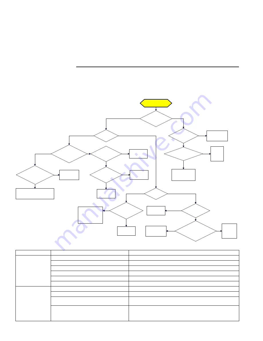
DSI Integrated Control Module (Circuit 

Board) Trial Troubleshooting Flowchart

Trial for Ignition

Call for Heat

Is there a

spark across gap at

ignitor?

Does gas

ignite?

Is there minimum

flame current at the

flame sensor?

Is there

minimum flame current

at the control

module?

Replace control

module.

Check connections to flame

sensor and/or moisture in the

burner assembly.

Is the flame

sensor corroded?

Clean flame

sensor.

Is the sensor

located in flame

correctly?

Replace flame

sesnsor.

Reposition

flame sensor.

Is gas

flowing?

Is the ignitor

position correct in the

gas flow?

Check gas pressure

 and supply voltage.

 If either are low,

 correct and repeat

startup.

Reposition

spark ignitor.

Is there

24VAC at the gas

valve?

Is there 24VAC

from gas valve output on

control module to

chassis?

Check wiring and

connections to

gas valve.

Replace

ignition

control

module.

Replace gas

valve.

Is there

spark voltage at

control?

Check high

voltage wire

continuity.

Is there 24V P1-2

to power control?

Replace

control

module.

Check wiring

and/or 24VAC

transformer output.

YES

NO

YES

NO

YES

NO

YES

NO

YES

NO

YES

NO

YES

NO

YES

NO

NO

YES

YES

NO

YES

NO

YES

NO

PROBLEM

PROBABLE CAUSE 

REMEDY

Venter motor will not 

start 

1. 

No power to unit.

1. 

Turn on power, check supply fuses or circuit breaker.

.

 No 24 volt power to integrated circuit board.

.

 Turn up thermostat; check control transformer output. 

3. 

Integrated circuit board fuse blown.

3. 

Correct cause. Replace fuse (type ATC or ATO, 32VDC, 3A).

4

. No power to venter motor.

4.

 Tighten connections at circuit board and/or motor terminals.

5

. Integrated circuit board defective.

5.

 Replace integrated circuit board.

6.

 Defective venter motor.

6. 

Replace venter motor.  See Paragraph 29.

Burner will not light

1.

 Manual valve not open.

1.

 Open manual valve.

.

 Air in the gas line.

Bleed gas line (initial startup only).

3. 

Gas pressure too high or too low.

3. 

Supply pressure should be 5" - 14" w.c. for natural gas or 11" - 14" w.c. 

for propane gas. 

4. 

No Spark:

4.

a) Loose wire connections.

a) Be certain all wire connections are solid.

b) Transformer failure.

b) Be sure 24 volts is available.

Содержание UDAP

Страница 1: ...iately call your gas supplier from a neighbor s phone Follow the gas supplier s instructions If you cannot reach your gas supplier call your fire department FOR YOUR SAFETY Do not store or use gasolin...

Страница 2: ...ration maintenance and service of this heater Definitions of Hazard Intensity Levels in this Manual Contents 1 General 2 4 1 1 Hazard Labels and Notices 2 1 2 General Installation Information 3 1 3 Wa...

Страница 3: ...BOTH this manual and the correct venting manual are REQUIRED for installation of this heater 1 2 General Installation Information WARNING Do not use this appliance if any part has been under water Imm...

Страница 4: ...garages in accordance with ANSI NFPA No 88B latest edition Standard for Repair Garages In Canada installations in aircraft hangars should be in accordance with the require ments of the enforcing auth...

Страница 5: ...24 16 29 93 21 15 28 94 24 17 31 105 20 18 34 113 17 10 ft 14 24 69 32 17 29 87 27 17 31 91 25 15 27 82 30 17 30 90 26 16 28 89 29 18 32 103 25 20 35 110 21 12 ft 14 24 64 39 18 29 84 32 18 31 88 30 1...

Страница 6: ...tions cont d 3 Uncrating and Preparation 3 1 Uncrating and Inspecting This unit was test operated and inspected at the factory prior to crating and was in operating condition If the heater has incurre...

Страница 7: ...60 75 100 125 150 175 200 225 250 300 350 400 High Altitude Switch P N 197031 197032 197031 201160 Negative Pressure OFF Setpoint w c 0 4 0 5 0 4 1 1 Label color Purple Pink Purple Brown Model UDAP CV...

Страница 8: ...1 4 5 7 16 6 1 2 25 11 16 1 3 8 8 3 16 22 3 16 16 3 8 225 250 26 1 8 38 3 16 22 23 42 35 3 8 13 1 16 8 13 16 9 6 1 2 25 11 16 1 3 8 8 3 16 22 3 16 15 5 8 300 350 400 34 1 8 41 30 23 42 35 3 8 17 1 16...

Страница 9: ...35 3 8 8 1 2 8 1 4 5 7 16 6 1 2 25 11 16 1 3 8 8 3 16 22 3 16 16 3 8 4 1 8 8 5 16 225 250 26 1 8 38 3 16 22 23 42 35 3 8 13 1 16 8 13 16 9 6 1 2 25 11 16 1 3 8 8 3 16 22 3 16 15 5 8 5 9 16 8 5 16 300...

Страница 10: ...spending the heater check the supporting structure to be used to verify that it has sufficient load carrying capacity to support the weight of the unit Model UDAP Size 30 45 60 75 100 125 150 175 200...

Страница 11: ...Retainers either two or four point suspension Be sure the threaded hanger rods are locked to the heater as illustrated Length of threaded rod extending into the heater MUST NOT exceed 1 2 13mm If ord...

Страница 12: ...service NEVER TEST FOR LEAKS WITH AN OPEN FLAME Failure to comply could result in personal injury property damage or death Capacity of Piping Cubic Feet per Hour based on 0 3 w c Pressure Drop Specif...

Страница 13: ...c and a maximum of 14 w c Before attempting to measure or adjust valve outlet gas pressure the inlet supply pressure must be within the specified range both when the heater is in operation and on sta...

Страница 14: ...above 6000 ft 1830M a high altitude pressure switch is required see Paragraph 3 2 1 Manifold Pressure Settings by Altitude for the UNITED STATES Altitude Natural Gas inches w c Propane Gas inches w c...

Страница 15: ...500 124915 105350 7001 8000 2136 2440 88200 74088 61740 100800 84672 70560 126000 104580 88200 147000 122010 102900 8001 9000 2441 2745 86100 72324 60270 98400 82656 68880 123000 102090 86100 143500 1...

Страница 16: ...outside air ducts voids the warranty and could cause hazard ous operation See Hazard Levels page 2 Do not install a unit in a confined space without providing wall openings leading to and from the spa...

Страница 17: ...he installation requires a stepdown trans former Option CG follow the instructions shipped with the option package for attach ing the transformer to the heater The electrical supply enters at the rear...

Страница 18: ...Form I UDA P N 195673 Rev 13 Page 18 7 Electrical Supply and Wiring cont d FIGURE 14A Typical Wiring Diagram for Model UDAP or Model UDAS Single Stage 7 4 Wiring Diagrams...

Страница 19: ...Form I UDA P N 195673 Rev 13 Page 19 FIGURE 14B Typical Wiring Diagram for Model UDAP or Model UDAS Single Stage with Optional Air Recirculation...

Страница 20: ...Form I UDA P N 195673 Rev 13 Page 20 FIGURE 14C Typical Wiring Diagram for Model UDAP or Model UDAS Two Stage Gas Valve 7 Electrical Supply and Wiring cont d 7 4 Wiring Diagrams cont d...

Страница 21: ...e vent system Hazardous conditions could result See Hazard Intensity Levels page 2 Model UDAP Startup Cold Equilibrium Hot Setpoint OFF Setpoint ON Label Color Switch P N Model UDAS Startup Cold Equil...

Страница 22: ...ce Section Paragraph 10 2 10 for information on probable causes and instructions on resetting the flame rollout switch For location see FIGURE 18 page 30 DANGER If the manual reset flame rollout switc...

Страница 23: ...trol offers a wide variety of input and output points that can be configured to meet a wide range of building management applications User selectable input types are Thermis tor 4 20 milliamp 1 5 volt...

Страница 24: ...lame has not been sensed during the first 16 seconds the control de energizes the spark output and keeps the gas valve energized for an additional one second flame proving period If flame is not prese...

Страница 25: ...tion If flame is not established on the second trial for ignition the control de energizes the gas valve energizes the fan blower motor on heat speed and venter motor remains energized The fan blower...

Страница 26: ...l flash rapidly when lockout is due to undesired flame Gas Valve Relay Fault If the control senses the gas valve as energized for more than one second when the control is not attempting to energize th...

Страница 27: ...rty damage personal injury or loss of life This appliance does not have a pilot It is equipped with an igni tion device which automatically lights the burner Do not try to light the burner by hand Bef...

Страница 28: ...performed turn off all electric power to the appliance 3 Open the access door 4 Turn the gas control knob clockwise to OFF Do not force 5 Close the access door FIGURE 17 Gas Valve ON OFF Control Knob...

Страница 29: ...soundness Clean openings Replace any parts that do not appear sound Check the wiring for any damaged wire Replace damaged wiring See Paragraph 7 for replacement wiring requirements 10 1 Maintenance Sc...

Страница 30: ...tion of dirt dust and or lint clean the compartment and follow the instructions below to remove and clean the burner Burner Removal Instructions Refer to FIGURE 19 CAUTION Use of eye protection is rec...

Страница 31: ...the burner ribbons Holding the burner assembly so that any foreign material will fall away from the burner use a stiff bristle brush to loosen and remove any foreign material s If the burner is excess...

Страница 32: ...to 1 8 See FIGURE 21 IMPORTANT When re assembling the brown ground wire must remain attached to the ignitor Ignitor CAUTION Due to high voltage on the spark wire and electrode do not touch when ener g...

Страница 33: ...fan guard Rotate the fan blade to check for adequate clearance If adjustment is required loosen the mounting screws re position the fan guard and tighten the screws Rotate the fan blade and re check f...

Страница 34: ...With the manual valve turned off to prevent flow to the gas valve connect a manometer to the 1 8 outlet pressure tap in the valve NOTE A manometer fluid filled gauge is recommended 3 Turn the manual...

Страница 35: ...ace If the flame rollout switch trips again determine and correct the cause before resetting the switch If there is damage to the control compartment repairs must be made before resetting the switch I...

Страница 36: ...Is the sensor located in flame correctly Replace flame sesnsor Reposition flame sensor Is gas flowing Is the ignitor position correct in the gas flow Check gas pressure and supply voltage If either ar...

Страница 37: ...Supply pressure should be 5 14 w c for natural gas or 11 14 w c for propane gas d Cracked ceramic at sensor d Replace sensor Burner cycle on and off 1 Gas pressure too high or too low 1 Supply pressu...

Страница 38: ...y line size C Smaller and or larger vent and combustion air pipe diameters may be permissible For Model UDAS refer to the Venting Installation Manual for Separated Combustion Units For Model UDAP refe...

Страница 39: ...lights 24 Limit Control 21 34 Limit Switch 25 Literature Bag 29 Location 5 Unit Heater Location 4 Location of Controls 30 Lockout 26 Optional vertical louvers 6 M Maintenance Procedures 30 Maintenanc...

Страница 40: ...____________________________________________________ Phone _________________________________ Model ________________ Serial No ______________________________Date of Installation ____________ SPECIFIC I...

Отзывы: