


8
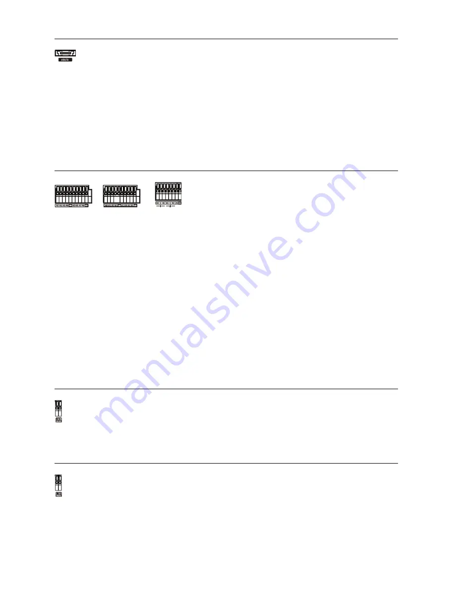
eSATA Port
CAUTION: Do NOT connect or disconnect eSATA devices while the DVR power is on. The
DVR must be powered down to connect or disconnect eSATA devices. Power up
eSATA devices so they are ready for operation before powering up the DVR. Power
down eSATA devices after powering down the DVR and then disconnect eSATA
devices.
CAUTION: If the eSATA device is shut down while the device is operating, the DVR system
might not operate normally.
Alarm Input/Output
AI 1 to 16 (Alarm-In)
: You can use external devices to signal the DVR to react to events. Mechanical or electrical
switches can be wired to the
AI
(Alarm-In) and
GND
(Ground) connectors. The threshold voltage of electrical
switches for NC (Normally Closed) is above 2.4V and for NO (Normally Open) is below 0.3V, and should be
stable at least 0.5 seconds to be detected. The voltage range of alarm input is from 0V to 5V.
GND (Ground)
: Connect the ground side of the Alarm input and/or alarm output to the GND connector.
NOTE: All the connectors marked GND are common.
NC/NO (Relay Alarm Outputs):
The DVR can activate external devices such as buzzers or lights. Connect
the device to the
C
(Common) and
NC
(Normally Closed) or
C
and
NO
(Normally Open) connectors.
NC/NO
is
a relay output which sinks 2A@125VAC and 1A@30VDC.
ARI (Alarm Reset In):
An external signal to the
Alarm Reset In
can be used to reset both the Alarm Out signal
and the DVR’s internal buzzer. Mechanical or electrical switches can be wired to the
ARI
(Alarm Reset In) and
GND
(Ground) connectors. The threshold voltage is below 0.3V and should be stable at least 0.5 seconds to
be detected. Connect the wires to the
ARI
and
GND
connectors.
RS485 Port
RS232 Port
An eSATA port is provided to connect external storage devices for recording video. Connect the
external eSATA hard disk drive (RAID) cable to the eSATA port.
NOTE: To make connections on the Alarm Connector Strip,
press and hold the button and insert the wire in the hole below
the button. After releasing the button, tug gently on the wire
to make certain it is connected. To disconnect a wire, press
and hold the button above the wire and pull out the wire.
The DVR can be controlled remotely by an external device or control system, such as a suitable control
keyboard, using RS485 half-duplex serial communications signals. The RS485 connector can also
be used to control PTZ (pan, tilt, zoom) cameras. Connect
RX+/TX+
and
RX-/TX-
of the control
system to the
P+
and
N–
(respectively) of the DVR.
An RS232 port is provided to connect a remote control keyboard.


