© RESOL 11294 flo
wsol_d_d_he
.monen.ind
d
FlowSol D / D HE
7 |
When you did not carry out the steps described in chapter
3.2, please carry out steps 1 to 5 of chapter 3.2 before you
carry out the following steps:
Î
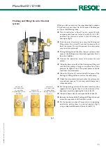
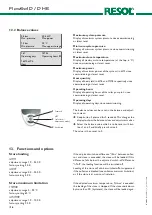
Turn the ball valves in flow (1) and in return (2) with
an open-ended spanner (wrench width 14) to a 45°
position. The non-return valves in the ball valves are
now open (fig. 4).
Î
Flush the solar thermal system using the flushing and
filling station for at least 15 minutes to remove all air
from the system. During this process, the solar pump
may run in manual mode.
Î
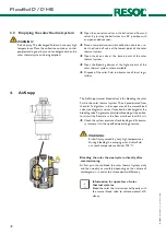
During flushing, bleed the solar thermal system several
times at the AirStopp until the discharged solar fluid is
free of air bubbles.
Î
Connect the expansion vessel to the solar thermal
system
Î
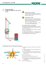
Close the drain valve (5) of the flushing and filling unit
with the filling pump running and increase the system
pressure to approx. 5 bar. The system pressure can be
read from the manometer
Î
Close the fill valve (3) and switch off the pump of the
flushing and filling station as well as the solar pump.
Î
Check the manometer to see whether the system pres-
sure reduces (approx. 15 minutes) and eliminate leaks
where necessary.
Î
Set the operating pressure of the solar thermal system
(approx. 0.5 bar higher than the inlet pressure of the
expansion vessel) by opening the drain valve (5).
Î
Close the drain valve (5) and open the ball valve (4).
Î
Remove the hoses of the flushing and filling station and
screw the caps onto the fill and drain valves.
Î
Put the non-return valves in flow and return in operating
position by putting them in a vertical position (fig. 4)
using an open-ended spanner (wrench width 14).
ball valve: 45°
non-return valve
not operating
flow-through in both
directions
ball valve: 90°
ball valve closed, no
flow-through
ball valve: 0°
non-return valve
in operation, flow-
through only in flow
direction
fig.3
fig.4
1
2
Flushing and filling the solar thermal
system

