background image


36 

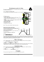
End stop 

The end stop operates the limit switch during the down movement of the chain and prevents the chain 
from running out of  the hoist. In  the unlikely event of a  failed limit switch the end stop operates as  an 
emergency stop and lets the clutch slide. It s not allowed to use this emergency stop permanently.


1.1.29 

Fitting the load chain 

– double fall version – 

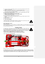
figure 12: Fitting the load chain for double fall version 

20. Insert the load chain as described in 3.1.6  
21. Insert the load chain into the sprocket wheel of the double fall hook with a special wire. 

     Caution!


Ensure that the load chain is not twisted between the chain guide of the hoist and the 
double  fall  hook.  This  would  be  dangerous.  If  it  is  not  possible  to  fit  the  load  chain 
according with figure 12 without being twisted one link has to be cut off. 


22. 

Remove the short piece of chain and the connecting piece.


23. Loosen the screws of the axle suspension. 
24. Loosen the two bolts of the chain suspension. 
25. Remove the chain suspension. 
26. Put the chain   - coming out of the double fall hook 

– into the pocket of the hoist without being twisted between the 

double fall hook and the hoist (see figure 12). 

27. Insert the chain suspension again. 
28. Secure the chain suspension with bolts. 
29. Fit the axle suspension and tighten the two screws. 
30. Check again that the chain is not twisted at all. 
31. 

Lower the load hook to it’s final position. 

32. Attach the end stop to the third chain link of the dead end. 
33. Fit the chain collector according to 3.1.5. 
34. Allow the chain to run into the chain bag by pressing the up button and lubricate the chain well. 


Hold down 
 
Chain guide 
 
Sprocket wheel 
 
Short  piece  of  chain 
to support the chain 
 
 
Connecting  piece  at 
the chain bag side 


Load chain 


Lift limiter 

Axle suspension 

Bolt for chain  

suspension  


chain suspension 


load chain 


double fall hook 

View from the motor side 

Screws 

for 

axle 
suspension  

Содержание LK-13 Series

Страница 1: ...GEBRUIKERSHANDLEIDING OWNER S MANUAL LK 13 series REMA HOLLAND BV Galjoenweg 47 6222 NS Maastricht Postbus 4303 6202 VA Maastricht Telefoon 0031 43 3631777 Fax 0031 43 3632922 Email info rema eu www...

Страница 2: ...ingskabel 22 Smering 23 Conformiteitsverklaring 25 PAGE OWNER S MANUAL Safety instructions 27 Technical overview 28 Assembly 30 Gear ventilation 33 Replacing oft he load chain chain guide and the hold...

Страница 3: ...ma eu Garantieaanvraag Registreer Uw product vandaag nog Garantianfrage Registrieren Sie ihr product heute Demande de garantie Registre votre produit aujourd hui Warranty request Register your product...

Страница 4: ...0...

Страница 5: ...opt als gevolg van zijn eigen gewicht op een veilige manier uit de lier kan bewegen Het negeren van bovenstaande instructie kan leiden tot het vastlopen van de ketting en als gevolg hiervan kan bescha...

Страница 6: ...rschriften in acht te worden genomen Werkzaamheden aan de elektrische kettingtakels mogen uitsluitend worden uitgevoerd door gekwalificeerde personen met een diploma van een vakopleiding na het uitsch...

Страница 7: ...enzer eindstop met rubberen stop Onderhaakset met rubberen stop Elektrische loopkatten Ophangplaat met n gat speciale uitvoering Onderhaakset enkel parts met rubberen stop Hangende schakelaar met nood...

Страница 8: ...ussenblok B 17 As met kettingtandwiel 7 Remeenheid 18 Deksel van de besturing die werkt op minimale 8 Ventilator spanning 9 Ventilatorschroef 19 Lastketting 10 Tandwiel II niet afgebeeld 20 Kettinggel...

Страница 9: ...racht Bij de montage van onderhaakset enkel partss moeten de schroefsluitingen met het onderstaande moment worden aangetrokken Onderdeel Max capaciteit kg Afmeting schroef Aantal Trekmoment Nm Onderha...

Страница 10: ...van de twee pennen in de hiervoor bedoelde boorgaten op de behuizing van de hijsinstallatie Plaats de sluitringen op de pennen en verzegel deze met de zekeringsmoeren Ophangplaat met n gat Zekeringsmo...

Страница 11: ...e twee pennen aan de op de kettingtakels aangebrachte bevestigingshaken Plaats de sluitringen op de pennen en verzegel deze met de zekeringsmoeren Let op De ophanghaak moet bij het veranderen van het...

Страница 12: ...ening op de lierbehuizing en zet hem vast met zeskant moer M8 30 DIN 933 en de bijbehorende sluitring Steek de laatste schakel van het onderste uiteinde van de veiligheidsketting 7x22 in de hiervoor b...

Страница 13: ...pen en smeer ondertussen de ketting over de gehele lengte in met olie Let op Bij het insteken van een lastketting en bij het veranderen van het aantal kettingen mag de oude ketting nooit helemaal uit...

Страница 14: ...chakel van het uit de haakbehuizing verwijderde kettingeinde in de holte bij de kettingbevestiging 8 Plaats de kettinghouder terug in de behuizing van de hijsinstallatie 9 Plaats de pennen terug op hu...

Страница 15: ...emonteer het deksel van de besturing van 24 V door 4 inbusbouten M6 75 DIN 912 te verwijderen 8 De demontage van de eindschakelaarsas van de eindstandbegrenzer dient te geschieden in onderstaande volg...

Страница 16: ...derkant van de behuizing 12 Duw de kettingneerdrukker met een schroevendraaier uit de kettingloop 13 Montage van de nieuwe kettingneerdrukker en de nieuwe kettinggeleider Het aandraaimoment van de 2 b...

Страница 17: ...de kettingtakels na een druk op de knop Hijsen in de hijsrichting De waarde van de zekering traag bij 400 V wisselstroom geplaatst v r de hoofdschakelaar van het net bedraagt 16 A Controleer of de ne...

Страница 18: ...ikt voor smalle balken volgens DIN 1025 en Euronorm 24 62 middelmatig brede I balken volgens DIN 1025 brede I balken volgens DIN 1025 Op het eind van het transporttraject dienen ter hoogte van het mid...

Страница 19: ...op een van de zijkanten een zekeringspen te vinden De zekeringsmoer van pen M36 1 5 van de loopkatten moet met behulp van een aandraaisleutel met een moment van 560 Nm worden aangedraaid Afbeelding 1...

Страница 20: ...en sleepinstallaties BGV D8 VBG 8 UVV Kranen BGV D6 VBG 9 Keuring bij gebruik volgens BGV D8 23 VBG 8 23 Men dient de kettingtakels voor de eerste ingebruikname en na essenti le veranderingen door ee...

Страница 21: ...anging haak van het hijswerktuig staat aangegeven Bedieningsverboden Het snel aan en uitschakelen van de functies Het bedrijfsmatige gebruik van een slipkoppeling direct werkende hijskrachtbeperking P...

Страница 22: ...ing dagelijks Elke 3 maanden Jaarlijks Inspectie van de algemene toestand Controle van functies Rem Lastbegrenzer Onderhoud en afstelling Rem Slipkoppeling Slijtage van de lastketting volgens punt 7 4...

Страница 23: ...gemeten Het luchtspleet is in de fabriek op 0 4 mm afgesteld Het luchtspleet wordt groter als gevolg van slijtage Als de remvoering zodanig versleten is dat het luchtspleet van de rem de maximaal toeg...

Страница 24: ...h tussen de motor en de rem zodat de onderdelen van de aandrijfeenheid die van de rem tot aan de last helemaal van vormsluitende verbindingen is voorzien de kracht kunnen doorgeven Ook in het geval va...

Страница 25: ...ptember 2002 1 1 17 Het smeren van de lastketting v r ingebruikname en tijdens het gebruik De lastketting dient v r de eerste ingebruikname in lastvrije toestand over de gehele lengte op de draaiopper...

Страница 26: ...heid De inschakelduur van elektrische kettingtakels volgens FEM 9 683 Het toegestane aantal inschakelingen en de inschakelduur ED mogen niet worden overschreden zie FEM 9 683 De toegestane inschakeldu...

Страница 27: ...t men rustpauzes in te lassen om de lier af te laten koelen Gebruik het langzame hijsen alleen voor het voorzichtig neerzetten en ophijsen van de last Het langzame hijsen is niet geschikt voor een vol...

Страница 28: ...n na ongeveer 20 000 hef zakcycli of n keer per jaar met lagervet ingevet worden maar bij zware bedrijfs omstandigheden vaker Smering van de loopkatten De tandwieltjes van de aandrijving de tanden van...

Страница 29: ...k op ander bedrijfsgebieden zijn hierin niet opgenomen Indien er veranderingen bijvoorbeeld lawaai trillingen groot stroomverbruik het opnieuw doorslaan van de stoppen optreden moet de installatie wor...

Страница 30: ...26...

Страница 31: ...27...

Страница 32: ...y and within the area of the European community the following regulations and all recommendations of this manual Please pay particular attention to the rules for the prevention of accidents and the st...

Страница 33: ...lleys and the installation of greater hoisting and operating heights Motorised trolley Suspension eye standard Chain box with safety chain End stop Double fall hook Suspension eye special Lifting gear...

Страница 34: ...3 Stator 13 Pinion shaft V without illustration 4 Rotor 14 Pinion shaft VII 5 Motor pinion shaft 15 Geared wheel VI 6 Bearing plate B 16 Geared wheel VIII 7 Brake unit 17 Sprocket wheel 8 Fan 18 Cover...

Страница 35: ...assembly 1 1 23 Hook tackle The hook tackle used to attach loads for hoists in single fall version figure 4 Single fall hook for 16x45 diameter chain If maintenance work is carried out don t is don t...

Страница 36: ...on eye section which forms part of the standard delivery must be inserted into the specially provided suspension holes on the electric chain hoist and pinned into place with the two bolts Use washers...

Страница 37: ...he blue arrows on the suspension eye and on the hoist body which have to be at the same side of the hoist If a hoist with a single hole eye has to be converted to a different number of load falls the...

Страница 38: ...ylock Please make sure that this chain is tighten and not twisted at all Caution Check if the size of the chain box at hand is sufficient to accommodate the respective chain length of the chain hoist...

Страница 39: ...op to the third chain link 8 Fit the chain collector according 3 1 5 9 Allow the chain running into the chain collector and lubricate the whole chain length well Caution When changing the load chain a...

Страница 40: ...e of chain and the connecting piece 23 Loosen the screws of the axle suspension 24 Loosen the two bolts of the chain suspension 25 Remove the chain suspension 26 Put the chain coming out of the double...

Страница 41: ...wn 30 Remove the cover of the contactor control four screws M6x75 DIN 912 31 Dismantle the shaft of the limit switches as follows Remove the two tension pins 5x30 Remove the snap ring and the torsion...

Страница 42: ...e two screws M16x120 DIN 912 of the chain guide in the control compartment of the hoist 8 Remove the chain guide underside of casing 9 Remove the hold down press it out with a screw driver 10 Insert t...

Страница 43: ...nt of mains switch is 16 A Check if the mains voltage agrees with that specified on the rating plate Connect mains current supply lines and control line in accordance with wiring diagram The terminals...

Страница 44: ...eration of the limit switches see 3 2 1 Figure 3 Electric limit switches Electric chain hoist with trolley All trolleys are suitable for Harrow I beams in accordance with DIN 1025 and European recomme...

Страница 45: ...g bolts To guarantee that the trolley can t be assembled in a wrong position one side plate carries a safety bolt The nylock nuts M36x1 5 of the suspension bolts have to be tightened with a torque wre...

Страница 46: ...rding to VBG 9 section 25 The cranes must be tested by an expert before starting operation for the first time and after extensive alterations The electric chain hoists are type tested Regular tests Th...

Страница 47: ...on the specification plate Transporting people Using the hoist with people being underneath the load Starting initial operation before an expert or a trained specialist has inspected the equipment Mov...

Страница 48: ...rication of the load chain lubrication of single and double fall hooks pressure bearing and wheel bearings check condition of safety latch and of the pin which prevent the hook nut from loosening univ...

Страница 49: ...e is released and the hoist is ready to lift or lower the load If the D C power is cut off the anchor plate moves back caused by force of the pressure springs the brake is closed and the load securely...

Страница 50: ...afe principle If there is a power failure the brake acts automatically so that the load is held securely in every position To shorten the braking distance the brake is operated in a D C circuit Slidin...

Страница 51: ...load chain must be lubricated with a penetrating gear lubricant oil before starting operation for the first time and during unloaded operation Subsequent lubrication whereby the links must be cleaned...

Страница 52: ...lowering break time time min running time to running time period of rest Formula 2 c d f ED running time x 100 running time period of rest The duty rate is limited by the permissible degree of heat in...

Страница 53: ...ate for electric trolley Strainer clamp for the control cable The strainer clamp must be fixed in such a way as to prevent any tensile forces affecting the control cable Pulling the chain hoist at the...

Страница 54: ...50...

Страница 55: ...51 www rema eu...

Отзывы: