Manual –TC.GXS
2016-09-16
11 / 43
Template V02.11
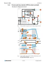
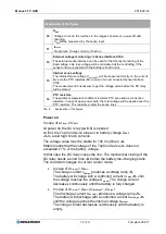
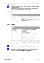
Explanation of the figures
1
U
Intern,
Internal voltage before the DC realay
Curve of the internal voltage in the ranges of power-on, power-off and
charging. If the DC relay is closed, the internal voltage U
Intern
equates to the
output voltage U
Rail
of the line rails.
2
U
Preset
At TopCon preset maximum voltage to charge the battery.
U
Preset
equates to the charging end voltage.
3
U
Batt
Curve of battery voltage.
4
Delay time
The internal controller circuit waits until the voltage across the DC relay is
stable enough for switching on the relay.
The threshold default value for overshoot: ± 1 % TopCon nominal voltage.
Default value: 100 ms
5
Ramp time
The internal controller circuit tries to reach the preset voltage U
Preset.
If the DC relay is closed, immediately the controller works as a current
controller. The charge current I
Charge
produces a voltage ramp.
6
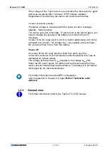
Battery is charged
The battery has reached the preset charging voltage U
Preset
, while the
TopCon device is running.
7
Period of charging
Time until the battery voltage U
Batt
equates to the charging end voltage.
U
Preset
equates to the charging end voltage on the best way.
8
Switch delay time
The mechanical switch of the DC relay needs a short time for connecting or
disconnecting. (Default value : up to 100 ms)
9
I
Charge,
Charge current curve
Charge current curve in the ranges of power-on, power-off and charging.
Tab. 8
Explanation of the figures. The table is continued on the next page.


