3-12
CHAPTER 3
Typical Catalyst Engine Monitoring Panel
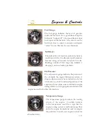
Shown is a typical dash mounted
engine emission status panel used with
catalyst engines. It provides a visual
and audible (beeping alarm) means
of monitoring engine and emission
control systems. The panel will show
the outline of an engine on the left side
and a warning sign on the right.
When an emissions related fault is detected an amber colored light will
appear on the left side.
When an engine related malfunction is detected the warning sign will
light red on the right side. If the situation is serious enough there may
be a signi
fi
cant power reduction of the engine.
If either of the above lights is lighted an audible short beep alarm will
be activated.
When the engine is initially started there is a series of self-checks
involving the various emission system sensors.
Read the engine manufacturer’s operation manual for more detailed
information on emission monitoring systems related to the particular
engine brand installed on your vessel.
Located at the helm is another indicator
device called a high water alarm. This
component warns the skipper of a possible
bilge emergency. There is an automatic
fl
oat
device installed at a predetermined bilge
level. If water rises over this level the bilge
switch sends a signal to the helm mounted
alarm. This
fl
oat device is mounted above the
normal positioning of the bilge pumps. If the alarm sounds bring the
vessel back to a idle position. Shift both engines into neutral and turn
off both ignition switches. Open the engine hatch and
fi
nd the cause
of the problem. Test before each outing. Refer to operation manual.
Содержание 3200 Bowrider
Страница 1: ...INT 1 OWNER S MANUAL 3200...
Страница 2: ...REGAL 321302 3200 Bowrider OWNER S MANUAL 10 2012...
Страница 7: ...INT 7 Introduction THIS PAGE IS LEFT INTENTIONALLY BLANK...
Страница 18: ...INT 18...
Страница 38: ...1 16 CHAPTER 1 NAVIGATION LIGHT RULES...
Страница 41: ...1 19 Safety On Board...
Страница 109: ...Vessel Operation 5 9...
Страница 150: ...CHAPTER 6 6 18 Canvas Typical PowerTower In Up Position w Sunshades...
Страница 155: ...Equipment Operation 6 23 Canvas Typical Storage Mooring Cover...
Страница 182: ...CHAPTER 6 6 50 Typical Hinged Power Tower Actuator Hydraulic Ram Typical Power Tower...
Страница 191: ...Equipment Operation 6 59...
Страница 192: ...CHAPTER 6 6 60...
Страница 193: ...Equipment Operation 6 61...
Страница 194: ...CHAPTER 6 6 62...
Страница 195: ...Equipment Operation 6 63...
Страница 196: ...CHAPTER 6 6 64...
Страница 197: ...Equipment Operation 6 65...
Страница 199: ...Equipment Operation 6 67...
Страница 200: ...CHAPTER 6 6 68...
Страница 278: ...CHAPTER 9 Notes...
Страница 290: ...11 4 TYPICAL LABEL PLACARD LOCATION PowerTower...
Страница 292: ...6 3200 BOW RIDER DECK HARDWARE 1 0F 2...
Страница 297: ...11 3200 BOW RIDER TYPICAL EPA COMPLIANT FUEL TANK INSTALLATION...
Страница 299: ...13 3200 BOW RIDER COLD WATER SYSTEM RUNS...
Страница 300: ...14 3200 BOW RIDER ELECTRIC TOILET W OVERBOARD DISCHARGE...
Страница 301: ...15 3200 BOW RIDER ELECTRIC TOILET W DECK PUMP OUT...
Страница 306: ...3200 BOW RIDER DC HEAD PANEL 20...
Страница 307: ...3200 BOW RIDER HELM SWITCH PANEL 21...
Страница 308: ...3200 BOW RIDER HELM BREAKER PANEL 22...
Страница 309: ...3200 BOW RIDER VOLVO IGN MERC ANALOG EVC 23...
Страница 310: ...3200 BOW RIDER IPA VOLVO MERC ANALOG 24...
Страница 311: ...3200 BOW RIDER IPA VOLVO MERC ANALOG W GARMIN 25...
Страница 312: ...3200 BOW RIDER BATTERY MANAGEMENT PANEL 26...
Страница 313: ...3200 BOW RIDER AFT SWITCH PANEL 27...
Страница 314: ...3200 BOW RIDER WINDLASS PANEL 28...
Страница 315: ...3200 BOW RIDER HEIGHT DIMENSIONS 30 1 1 2 54 1 4 101 3 4 8 5 3 4 3 1 4 45 3 4 58 3 15 12...
Страница 316: ...3200 BOW RIDER STANDARD SEATING POSITIONS 31...


