7-14
CHAPTER 7
Bilge Pump
A bilge pump is usually
installed in the engine
compartment just below
the engine front. Check for
foreign materials stuck in
the strainer area or discharge
hose.
Check all clamps and electrical
connections for tightness. A
quick check of the bilge
pump automatic
fl
oat switch
when installed is afforded
by lifting up on the float
and listening for the pump
operating. Look around the
fl
oat area for foreign debris
and remove as necessary.
Other vessels host a second bilge pump normally found at the forward
or mid hull positions to capture trapped water in this section of the
vessel.
It may sometimes become necessary to replace the bilge pump
impeller. Unfasten the bilge pump housing from the unit by pressing
on the quick release tabs on the grate and pulling up, similar to a
quick disconnect clip on a backpack. Remove the o-ring and access
the impeller. Remove any debris lodged in the impeller and replace
if fractured in any form. Then reinstall the unit as before. The bilge
pump impeller should be changed as often as every couple years.
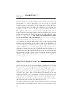
AUTOMATIC FLOAT SWITCH
BILGE
PUMP
CHECK
FOR DEBRIS
TYPICAL BILGE PUMP
Содержание 3200 Bowrider
Страница 1: ...INT 1 OWNER S MANUAL 3200...
Страница 2: ...REGAL 321302 3200 Bowrider OWNER S MANUAL 10 2012...
Страница 7: ...INT 7 Introduction THIS PAGE IS LEFT INTENTIONALLY BLANK...
Страница 18: ...INT 18...
Страница 38: ...1 16 CHAPTER 1 NAVIGATION LIGHT RULES...
Страница 41: ...1 19 Safety On Board...
Страница 109: ...Vessel Operation 5 9...
Страница 150: ...CHAPTER 6 6 18 Canvas Typical PowerTower In Up Position w Sunshades...
Страница 155: ...Equipment Operation 6 23 Canvas Typical Storage Mooring Cover...
Страница 182: ...CHAPTER 6 6 50 Typical Hinged Power Tower Actuator Hydraulic Ram Typical Power Tower...
Страница 191: ...Equipment Operation 6 59...
Страница 192: ...CHAPTER 6 6 60...
Страница 193: ...Equipment Operation 6 61...
Страница 194: ...CHAPTER 6 6 62...
Страница 195: ...Equipment Operation 6 63...
Страница 196: ...CHAPTER 6 6 64...
Страница 197: ...Equipment Operation 6 65...
Страница 199: ...Equipment Operation 6 67...
Страница 200: ...CHAPTER 6 6 68...
Страница 278: ...CHAPTER 9 Notes...
Страница 290: ...11 4 TYPICAL LABEL PLACARD LOCATION PowerTower...
Страница 292: ...6 3200 BOW RIDER DECK HARDWARE 1 0F 2...
Страница 297: ...11 3200 BOW RIDER TYPICAL EPA COMPLIANT FUEL TANK INSTALLATION...
Страница 299: ...13 3200 BOW RIDER COLD WATER SYSTEM RUNS...
Страница 300: ...14 3200 BOW RIDER ELECTRIC TOILET W OVERBOARD DISCHARGE...
Страница 301: ...15 3200 BOW RIDER ELECTRIC TOILET W DECK PUMP OUT...
Страница 306: ...3200 BOW RIDER DC HEAD PANEL 20...
Страница 307: ...3200 BOW RIDER HELM SWITCH PANEL 21...
Страница 308: ...3200 BOW RIDER HELM BREAKER PANEL 22...
Страница 309: ...3200 BOW RIDER VOLVO IGN MERC ANALOG EVC 23...
Страница 310: ...3200 BOW RIDER IPA VOLVO MERC ANALOG 24...
Страница 311: ...3200 BOW RIDER IPA VOLVO MERC ANALOG W GARMIN 25...
Страница 312: ...3200 BOW RIDER BATTERY MANAGEMENT PANEL 26...
Страница 313: ...3200 BOW RIDER AFT SWITCH PANEL 27...
Страница 314: ...3200 BOW RIDER WINDLASS PANEL 28...
Страница 315: ...3200 BOW RIDER HEIGHT DIMENSIONS 30 1 1 2 54 1 4 101 3 4 8 5 3 4 3 1 4 45 3 4 58 3 15 12...
Страница 316: ...3200 BOW RIDER STANDARD SEATING POSITIONS 31...


