4
Chapter 5
NOTE
:
Turn the ignition key to the right “OPERAT-
ING” position and then to the spring loaded “START”
position. At this point the key can be released and
the engine will crank until it starts.
To stop the engine,
return the key to the “off ” position. On select engines
the stop position is straight up and down; others the stop
function is at a 180 degree position.
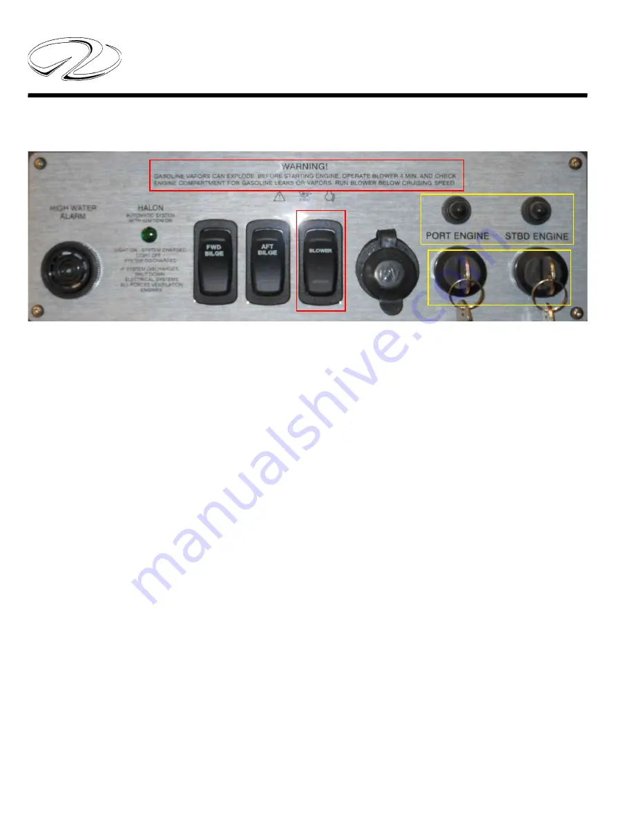
IGNITION SWITCH PANEL
Ignition key switches normally feature the following posi-
tions to identify key operating areas.
S= Stop
I= Operating Position (Ignition On)
II-III=Start (Spring Loaded)
Notice the areas above outlined in red as they refer to
important safety information. Read and understand the
blower information before attempting to start the engines.
The blower switch above is used on all gasoline engines.
Before turning on the blower switch do a snife test by
opening the engine hatch. At the same time check fuel
tank components. When assured the bilge is clear of any
fumes turn on the blower switch for at least 4 minutes
before attempting to start the engines. This will vacate
any gasoline fumes that are in the engine room (bilge or
sump). Continue to run the powered blower system below
cruising speeds after starting the engines.
Diesel engines on the other hand relay on natural ventila-
tion as the soul ingredient to develop engine horsepower
and to purge the bilge area.
The areas in yellow represent 20 amp ignition system break-
ers. There is one breaker per key switch. These breakers
protect the ignition switch circuitry. Should a breker “pop”
fi nd the cause of the malfunction before attempting to
restart the engine.
Содержание 32 EXPRESS
Страница 1: ...2011 Sport Yacht Collection S Y h C ll 32 EXPRESS OWNER S MANUAL...
Страница 3: ...320102 12 6 2013 OWNER S MANUAL 32 EXPRESS...
Страница 32: ...11 Safety On Board NAVIGATION LIGHT RULES...
Страница 53: ...9 Rules Of The Road...
Страница 54: ...10 Chapter 3...
Страница 94: ...40 Chapter 4 TYPICAL 12 VOLT HELM SWITCH PANEL...
Страница 106: ...52 Chapter 4 TYPICAL ELCI AC CIRCUIT FLOW CHART VOLTS VOLTS VOLTS VOLTS LINE...
Страница 148: ...94 Chapter 4...
Страница 149: ...95 Systems...
Страница 150: ...96 Chapter 4...
Страница 151: ...97 Systems...
Страница 152: ...98 Chapter 4...
Страница 153: ...99 Systems...
Страница 154: ...100 Chapter 4...
Страница 155: ...101 Systems...
Страница 156: ...102 Chapter 4...
Страница 157: ...103 Systems...
Страница 158: ...104 Chapter 4...
Страница 159: ...105 Systems...
Страница 180: ...15 Engine Controls AFT FORWARD SIDEWAYS DIAGONALLY ROTATE JOYSTICK FUNCTIONS...
Страница 262: ...22 Chapter 8 OVERBOARD DISCHARGE PAN DRAIN TYPICAL VECTOR COMPACT AC SYSTEM AIR FILTER...
Страница 276: ...36 Chapter 8...
Страница 300: ...9 Troubleshooting STEREO DIAGNOSTIC CHART...
Страница 301: ...10 Chapter 9 STEREO DIAGNOSTIC CHART...
Страница 302: ...11 Troubleshooting STEREO DIAGNOSTIC CHART...
Страница 303: ...12 Chapter 9 TACHOMETER ELECTRONIC DIESEL...
Страница 304: ...13 Troubleshooting TACHOMETER ELECTRONIC DIESEL...
Страница 307: ...16 Chapter 9 THRUSTER BOW...
Страница 309: ...18 Chapter 9 TYPICAL WINDLASS...
Страница 329: ...6 Chapter 12 TECHNICAL DRAWINGS...
Страница 330: ...Technical Information 12 7 32 EXPRESS GALVANIC ISOLATOR WIRING...
Страница 331: ...Technical Information 12 8 TYPICAL NMEA 2000 NETWORK COMPONENTS...
Страница 332: ...Technical Information 12 9 32 EXPRESS ELCI AC CIRCUIT FLOW CHART TYPICAL...
Страница 333: ...Technical Information 12 10 32 EXPRESS MAIN AC SHIP S PANEL FRONT VIEW...
Страница 334: ...Technical Information 12 11 32 EXPRESS MAIN AC SHIP S PANEL REAR VIEW...
Страница 335: ...Technical Information 12 12 32 EXPRESS MAIN DC SHIP S PANEL FRONT VIEW...
Страница 336: ...Technical Information 12 13 32 EXPRESS MAIN 12 VOLT DC SHIP S PANEL WITH BREAKER SIZES REAR VIEW...
Страница 337: ...Technical Information 12 14 32 EXPRESS COCKPIT SWITCH PANEL...
Страница 338: ...Technical Information 12 15 32 EXPRESS BATTERY VSR CIRCUITRY...
Страница 339: ...Technical Information 12 16 32 EXPRESS BATTERY MANAGEMENT PANEL...
Страница 340: ...Technical Information 12 17 32 EXPRESS HELM SWITCH PANEL...
Страница 341: ...Technical Information 12 18 32 EXPRESS HELM BREAKER PANEL...
Страница 342: ...Technical Information 12 19 32 EXPRESS VOLVO IGN MERC ANALOG EVC...
Страница 343: ...Technical Information 12 20 32 EXPRESS FIREWALL TO MDP HARNESS ROUTING...
Страница 344: ...Technical Information 12 21 32 EXPRESS DECK HARNESS ROUTING FORWARD...
Страница 345: ...Technical Information 12 22 32 EXPRESS DECK HARNESS ROUTING AFT...
Страница 346: ...Technical Information 12 23 32 EXPRESS HULL HARNESS ROUTING...
Страница 347: ...Technical Information 12 24 32 EXPRESS GAUGE PANEL CONFIGURATIONS...
Страница 348: ...Technical Information 12 25 32 EXPRESS TYPICAL DC GROUND CIRCUITRY...
Страница 349: ...Technical Information 12 26 32 EXPRESS TYPICAL TRIM TAB SWITCH CIRCUITRY...
Страница 350: ...Technical Information 12 27 32 EXPRESS TYPICAL BATTERY MANAGEMENT PANEL CIRCUITRY...
Страница 351: ...Technical Information 12 28 32 EXPRESS TYPICAL GFCI CIRCUITRY...
Страница 352: ...Technical Information 12 29 32 EXPRESS TYPICAL FIRE EXTINGUISHER GROUND CIRCUITRY...
Страница 353: ...Technical Information 12 30 32 EXPRESS STEREO BLUETOOTH WIRING...
Страница 357: ...Technical Information 12 34 32 EXPRESS MACHINERY LAYOUT...
Страница 358: ...Technical Information 12 35 32 EXPRESS FUEL TANK EPA COMPLIANT...
Страница 361: ...Technical Information 12 38 32 EXPRESS COCKPIT SEATING POSITION PLAN...
Страница 362: ...Technical Information 12 39 32 EXPRESS RANGE OF VISIBILITY...
Страница 363: ...Technical Information 12 40 32 EXPRESS DIMENSIONS APPROXIMATE...
Страница 364: ...Technical Information 12 41 32 EXPRESS BOW PLAN WINDLASS...


