75
g) Switching the video transmission frequency
The video transmitter in the quadrocopter operates in the 5.705 to 5.945 GHz frequency range. If there is interfer-
ence on the current frequency or if the frequency is being used by other devices, the transmission frequency can be
changed. Five frequency ranges (A - E) each with eight frequencies (1 - 8) are available.
Please see the following table for a precise overview (frequencies in GHz):
1
2
3
4
5
6
7
8
A
5.865
5.845
5.825
5.805
5.785
5.765
5.745
5.725
B
5.733
5.752
5.771
5.790
5.809
5.828
5.847
5.866
C
5.705
5.685
5.665
5.645
5.885
5.905
5.925
5.945
D
5.740
5.760
5.780
5.800
5.820
5.840
5.860
5.880
E
5.658
5.695
5.732
5.769
5.806
5.843
5.880
5.917
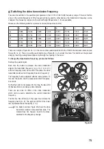
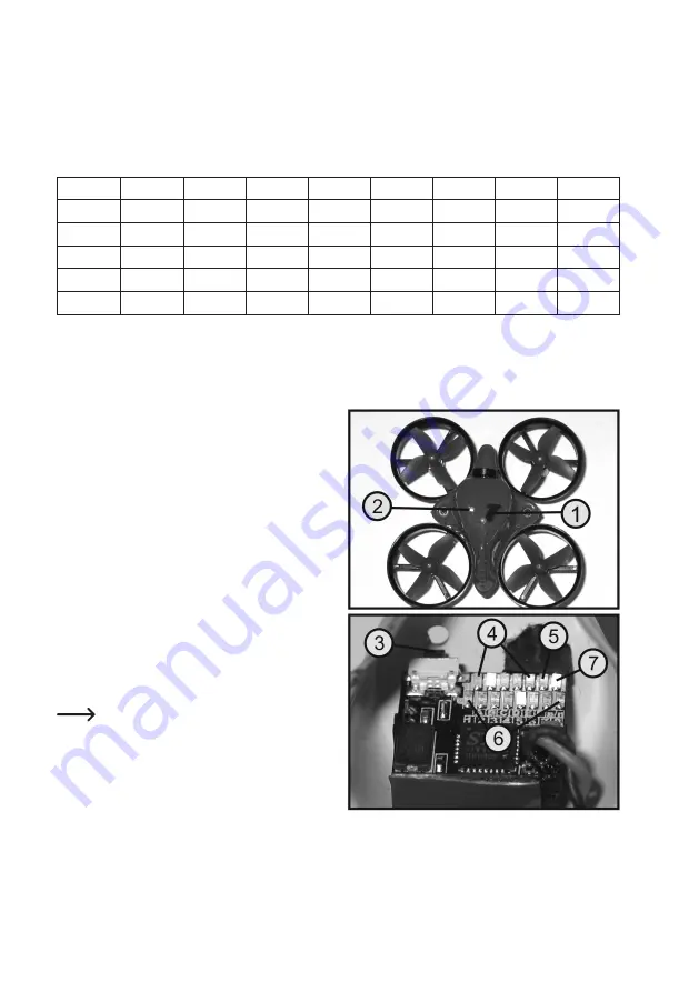
There is a hole (see Figure 26, no. 1) in the cover on the quadrocopter next to the 5.8 GHz transmission antenna (see
Figure 26, no. 2). There is a setting push button (see Figure 26, no. 3) under this hole. This button can be pressed
easily by inserting a straightened paper clip through the opening in the cover.
To change the transmission frequency, proceed as follows:
Start up the quadrocopter.
Each time the button is pressed, the video transmitter
adjusts the transmitter frequency (e.g. 2 to 3 or 4 to 5)
within a frequency band. At the end of the table, the video
transmitter switches from frequency 8 back to frequency 1.
The frequency band is adjusted with the same pattern. To
this end, the button must be pressed and held for approx.
2 seconds.
So that the button is not pressed for too long, the blue LED
(5) flashes after 2 seconds as a time indicator.
There are two rows of LEDs on the video transmitter
which can be used to determine the current transmitter
frequency.
The first five blue LEDs (4) in the upper row indicate the
frequency band (A - E). The eight red LEDs in the lower
row (6) indicate the set frequency (1 - 8).
For a better overview, Figure 26 shows the video
transmitter module in disassembled state. The
module does not, however, need to be disas-
sembled for the frequency change.
Figure 26

