


66
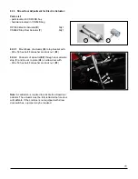
7.6 Top Ladder Step Installation
Parts List:
part included in CS975BS box
hardware located in CS859S bag
CS1026B
Step Top Ladder
(V)
Qty 1
7.6.3
Install Top Step (
V
)
onto upper flange
(W)
between
ladder rails (
G
) with:
- M10 x 25 round head bolt and flange nut (
V1
) x4
- insert bolts from above
V
V1
V
E2
7.6.1
Ensure ladder (
E2
) is mounted on ladder rails (
M
)
prior to installing top step (
V
)
7.6.2
Slide ladder (
E2
) up until ladder top step is above
floor of engine service area, hold or block in place
M
M
G
G
7.6.4
Ladder now can be unblocked and slid down so
that the ladder top step seats in lip of top step
W
Содержание Case IH AFX 120 Series
Страница 22: ...22 2 6 1 Disconnect LH Tank Cross Over LIne 2 6 1 1 Add plug A 2 6 2 Remove LH Tank Vent LIne A...
Страница 23: ...23 2 6 2 1 Remove Tank Cover Plate 2 6 2 2 Remove hose and tank fitting...
Страница 34: ...34 3 7 1 1 47776423 DEF Bundle Tank to Supply Module...
Страница 36: ...36 3 7 2 Extending DEF Lines 3 7 3 Extending Coolant Lines...
Страница 37: ...37 3 7 4 47776423 DEF Bundle Tank to Supply Module...


