background image

PT
-26

0


Ba
se

 A

s

se

m

b

ly


Содержание PT260

Страница 1: ...PLANER THICKNESSER WOODWORKING MACHINE PT260 USER S OPERATING MANUAL SERVICE INSTRUCTIONS CAUTION Read the instruction manual before using the appliance ...

Страница 2: ...nformation or drawings may not be intended directly for the machine purchased by you as these instructions contain any information for various variants of this type made by our company By comparing the respective part of the instructions with a particular machine you will find out whether or not they correspond to each other The manufacturer reserves the right to make partial alterations within co...

Страница 3: ...ing If it is necessary to remove the doors or protective covers turn off the switch and disconnect the plug from its socket Kick back catchers must be freely movable and their functioning must be checked regularly maybe several times a day Do not connect the machine to the mains while the door or protective cover is removed In order to avoid improper operation get acquainted with the location of s...

Страница 4: ...shoes recommended or prescribed by labour safety regulations of all countries Wear safety outfit goggles apron safety shoes hearing protection etc In the case of any obstacles above your head in the working area wear a helmet Always wear a protective mask while machining any material that produces dust while being machined Never wear any loose working clothes Do not work on the machine under influ...

Страница 5: ...th products having the same specifications as the original ones Do not remove or interfere otherwise in safety devices such as covers limit switches and do not block them mutually Do not switch the machine on before all covers removed for the purposes of maintenance are put in their places again Always keep the maintenance area including the working place clean Any maintenance work must be done by...

Страница 6: ...ssive vibrations and humidity It should be stored in a shelter at temperatures ranging from 25 C to 55 C As standard the machine is wrapped up in a plastic tray and is transported this way Upon request the machine may also be packed in a robust wooden box Technical specifications Machine Length mm 1125 Machine width mm 700 Machine height mm 955 Table height mm 830 Table of planing machine mm 1125X...

Страница 7: ...sources of noise etc e g the number of machines and the other neighbouring procedures Also the highest permissible levels of exposure may vary in different countries This information should help the machine user to evaluate the risk and the risk rate in a better manner Features and Terminology Receiving Carefully unpack the machine and any loose items from the wood crate and inspect for damage Any...

Страница 8: ...rce unplugged Failure to comply may result in serious injury The Model PT310 Jointer Planer is rated at 230V This machine is not supplied with a plug Use a plug and outlet rated at least 20amps The circuit for the machine should also be protected by at least a 20 amp circuit breaker or fuse Make sure that the cutterhead moves in thecorrect direction If it does not simply reverse two of the phase w...

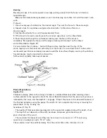
Страница 9: ...owered to allow clearance needed to position the dust chute Planer to Jointer Setup Referring to Figure 3 To change the machine configuration from planer to jointer 1 Pull the release knob F and reposition the dust chute D G to the left It should be positioned as shown in D Fig 2 Table is heavy Use care when lowering Failure to comply may cause serious injury 2 Release the latch E and bring the ta...

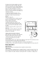
Страница 10: ...B Fig 4 to stop Planer Controls and Adjustments Referring to Figure 5 Power Feed Placing the planer power feed handle D in the up position turns the planer power feed on see arrow Placing the handle in the down position turns the power feed off Table Lock Turn the table lock E clockwise to lock the height adjustment handwheel F and secure the ...

Страница 11: ...he cabinet Jointer Controls and Adjustments Referring to Figure 6 Outfeed Table Height Adjustment Lock knob C and lifting handle B control the height adjustment of the outfeed table A The outfeed table is initially adjusted at the factory and should not be repositioned except during certain adjustments Infeed Table Height Adjustment Lock knob D and lifting handle E control the height adjustment of...

Страница 12: ...rd To tilt fence backward The fence A can be tilted backward D up to 45 that is for a total included angle of 135 from table surface as follows 1 Loosen locking handles F 2 Tilt the fence back A C to the desired angle up to 135 degrees Or you can place your beveled reference piece on the table and against the fence adjusting the fence until the angle of the fence matches the bevel of your gauge pi...

Страница 13: ...ich should be accurate enough for most purposes Important The tables must be locked in position when performing the following test Referring to Figures 8 and 9 1 Disconnect jointer from power source 2 Loosen the lock knob A and slide the cutterhead guard B C to clear the table 3 Slide the fence assembly back H E as far as it will go or remove it from the machine entirely 4 Rotate the cutterhead to...

Страница 14: ... table Adjusting the two right setscrews will have greatest adjustment impact to the table s right side adjusting the two left setscrews will have greatest adjustment impact to the table s left side 3 When adjustment is complete tighten the hex cap screws B1 Front adjustment Tools required two 13mm wrenches 1 Hold the hex cap screws A1 in place with one wrench while using the other to loosen the l...

Страница 15: ... 12 o clock position of knife number one The 12 o clock position is the highest point a blade will reach in the cutting arc C Fig 12 5 Set a straightedge J on the outfeed table F near the fence H One end of the straightedge should be positioned over the cutting knife C near the end of the blade as shown in Fig 9 Use care when handling the straightedge near the blades to prevent damage Note the pos...

Страница 16: ...into the knife slot making sure it faces the proper direction 8 Insert lock bar B and tighten just enough to hold in place 9 Repeat for other two blades Jointer Table Lock Handle Adjustment For best performance the jointer table lock handles A2 should be approximately in the fully down position when in the locked position If adjustment is required 1 Disconnect machine from power source 2 Unlock th...

Страница 17: ... Remove the feed roller belt G from around the feed roller pulley K and motor pulley M 9 Loop the new belt around the smaller inner motor pulley M and feed roller pulley K Note The lower stretch of the feed roller pulley must be positioned between the beltbrake plates N Concluding Steps 10 Replace the cutterhead drive belt F by looping it around the cutterhead pulley E then the larger outside moto...

Страница 18: ...distance from the table to tip of the knife blade is the same at both ends the table is parallel to the cutterhead Adjusting Work Table Parallel to Cutterhead If the work table is not parallel to the cutterhead perform the adjustment procedure as follows 7 With a 13mm wrench loosen four hex cap screws H located at each corner of the column support J 8 Bring the table parallel to the cutterhead by ...

Страница 19: ...the outfeed table The left hand is transferred to the outfeed side Figure 16 and presses down on this part of the workpiece at the same time maintaining flat contact with the fence The right hand presses the workpiece forward and before the right hand reaches the cutterhead it should be moved to the work on the outfeed table Surfacing The purpose of planing on a jointer is to produce one flat surf...

Страница 20: ...an 3 inches lap the fingers over the top of the wood extending them back over the fence such that they will act as a stop for the hands in the event of a kickback Position the fence move forward to expose only the amount of cutterhead required When workpiece is twice the length of the jointer infeed or outfeed table use an infeed or outfeed support To edge 1 Make sure the fence is set to 90 Double...

Страница 21: ...ood less than 3 inches wide use beveled push blocks and apply pressure toward the fence Keep fingers near top of push block Several passes may be required to achieve the full bevel will probably take several passes Planer Operations Depth of Cut Thickness planing refers to the sizing of lumber to a desired thickness while creating a level surface parallel to the opposite side of the board Board th...

Страница 22: ...hat encounters planer blades may be forcibly ejected from the planer creating a risk of injury Preparing the Work A thickness planer works best when the lumber has at least one flat surface Use a jointer to create a flat surface Twisted or severely warped boards can jam the planer Rip the lumber in half to reduce the magnitude of the warp The work should be fed into the planer in the same directio...

Страница 23: ...tfeed roller starts advancing it Move to the rear and receive the planed board by pushing it up when the infeed roller looses contact with the board When planning more than one board of the same thickness butt the boards together to avoid snipe Make shallow cuts Snipe is more apparent when deeper cuts are taken Feed the work in the direction of the grain Work fed against the grain will have chippe...

Страница 24: ...e the same amount of passes for all three blades When the blades have been sharpened and still are not cutting efficiently trying to touch up the blades further will only cause the formation of a second beveled edge When this starts to happen it is time to replace blades with another set It is recommended to keep a second set of blades on hand so that they may be installed while the first set is b...

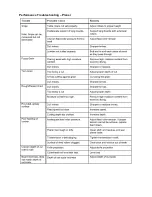
Страница 25: ...Troubleshooting Performance Troubleshooting Jointer ...

Страница 26: ...Performance Troubleshooting Planer ...

Страница 27: ...Mechanical Troubleshooting Planer Jointer ...

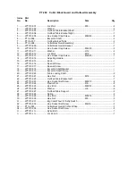
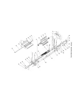
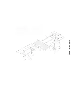
Страница 28: ...PT 260 Cutter Block Guard and Outfeed Assembly ...

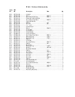
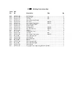
Страница 29: ...14 Adjusting Handle 1 15 JPT310 015 Knob 1 16 JPT310 016 Special Screw 1 17 JPT310 017 Special Screw 1 18 JPT310 018 Eccentric Shaft Bracket 1 19 JPT310 019 Eccentric Shaft Clamp 1 20 JPT310 020 Table Locking Shaft 2 21 JPT310 021 Hex Nut M12 2 22 JPT310 022 Outfeed Table Bracket Left 1 23 JPT310 023 Hex Socket Set Screw M8X10 8 24 JPT310 024 Plastic Disc D6 8 25 JPT310 025 Hex Bolt M8X30 6 26 JPT...

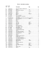
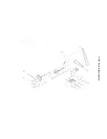
Страница 30: ...PT 260 Cutter Block assembly ...

Страница 31: ...10 080 Adjusting Washer 27 81 JPT310 081A Anti Kickback Finger 18 82 PT260 082 Infeed Roller 1 83 PT260 083 Anti Kickback Shaft 1 84 PT260 084 Cutterblock Cover 1 85 JPT310 085 Cutterblock Bracket Right 1 86 JPT310 086 Washer M6 4 87 JPT310 087 Hex Socket Cap Screw M6X12 4 88 JPT310 088 Cutterblock Bracket Cover 1 89 JPT310 089 Pan Head Screw M6X12 2 90 JPT310 090 Cap Nut M6 1 91 JPT310 091 Spring...

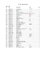
Страница 32: ...PT 260 Base Assembly ...

Страница 33: ...149 JPT310 149 Pan Head Screw M4X16 4 150 JPT310 150E Plug 230 50 1 1 JPT310 150AE Plug 400 50 1 1 151 JPT310 151 Special Bolt 4 152 JPT310 152 Hex Nut M8 4 153 JPT310 153 Lock Handle For Outfeed Table 1 154 JPT310 154 Retaining Ring CLP20 4 155 JPT310 155 Spring 2 156 JPT310 156 Direction Label 1 157 JPT310 157E Switch 230 50 1 1 JPT310 157AE Switch 400 50 3 1 158 JPT310 158 Pan Head Screw N4X60 ...

Страница 34: ...PT 260 Infeed Table Assembly ...

Страница 35: ...10 182 Outfeed Table Bracket Shaft 1 184 JPT310 184 Infeed Table Bracket Right M8X60 2 190 JPT310 190 Infeed Table Bracket Left 1 203 JPT310 203 Hex Socket Cap Screw M8X10 1 209 JPT310 209 Hex Socket Cap Screw M8X35 1 210 JPT310 210 Table Stopper 1 211 JPT310 211 Hex Nut M8 3 ...

Страница 36: ...PT 260 Drive and Motor Assembly ...

Страница 37: ... 232 JPT310 232 Hex Socket Set Screw M5X10 2 233 PT310W 233 Pulley for Feed Roller 1 234 JPT310 234 Cam Wheel 1 235 JPT310 235 Bearing 6000 2Z 2 236 JPT310 236 Spacer Bearing 1 238 JPT310 238 Hex Socket Set Screw M8X12 2 239 PT310W 239 Motor Pulley 1 240 PT310W 240 Micro V Belt for Feed Roller 1 241 JPT310 241 Hex Bolt M8X25 4 242 JPT310 242 Washer H8 4 243 PT260 010E Motor 230 50 1 1 PT260 010AE ...

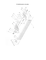
Страница 38: ...PT 260 Thickness Table Assembly ...

Страница 39: ...312 JPT310 312 Retaining Ring Clp20 1 313 JPT310 313 Retaining Ring Clp35 1 314 JPT310 314 Washer 1 315 JPT310 315 Crank Bar 1 316 JPT310 316 Pan Head Screw M6x12 2 317 JPT310 317 Washer M6 2 318 JPT310 318 Bevel Gear 2 319 JPT310 319 Retaining Ring Clp35 1 320 JPT310 320 Bearing 6202 2Z 1 321 JPT310 321 Bevel Gear Bracket 1 322 JPT310 322 Washer H8 8 323 JPT310 323 Hex Bolt M8x35 8 324 JPT310 324...

Страница 40: ...PT 260 Working Fence Assembly ...

Страница 41: ... 377 JPT310 377 Nylon Washer 9 378 JPT310 378 Carriage Bolt M8X25 2 379 JPT310 379 Pan Head Sscrew M6X12 6 380 JPT310 380 Washer H6 6 381 PT260 381 Cutterblock Cover 1 382 JPT310 382 Lock Nut M6 4 383 JPT310 383 Hex Socket Cap Screw M6X10 4 384 PT260 384 Fence Bracket Left 1 385 JPT310 385 Lock Handle 3 386 JPT310 386 Special Washer 2 387 PT260 387 Fence 1 388 JPT310 388 Fence Support Left 1 389 P...

Отзывы: