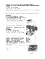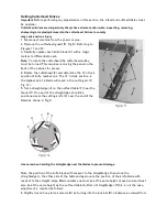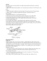
the infeed table (G).
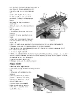
7. Adjust the blade height by turning jack screws (D) upon which the blades rest. To lower the
blade, turn the screw clockwise. To raise, turn the screw counter-clockwise.
8. When the blade is at the proper height, alternately tighten the five gib lock screws(A).
Repeat steps 4
–
8 for blades two and three.
Replacing Cutter Knives
Disconnect machine from power source before making any adjustments. Failure to comply may cause
serious injury.
1. Disconnect machine from the power source.
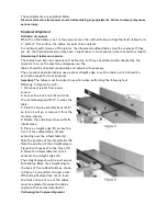
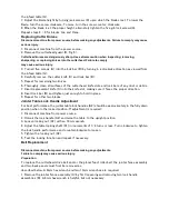
2. Remove the cutterhead guard (B, Fig. 6).
Cutterhead knives are dangerously sharp. Use extreme caution when inspecting, removing,
sharpening, or replacing knives into the cutterhead. Failure to comply
may cause serious injury.
3. Turn all five screws (A) into the lock bar (B) by turning in a clockwise direction as viewed from
the infeed table (G).
4. Carefully remove the cutter knife (C) and lock bar (B).
5. Repeat for remaining two knives.
6. Thoroughly clean all surfaces of the cutterhead, knife slots and lock bars of any dust or debris.
7. Insert replacement knife (C) into the knife slot, making sure it faces the proper direction.
8. Insert lock bar (B) and tighten just enough to hold in place.
9. Repeat for other two blades.
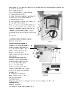
Jointer Table Lock Handle Adjustment
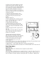
For best performance, the jointer table lock handles (A2) should be approximately in the fully down
position when in the locked position. If adjustment is required:
1. Disconnect machine from power source.
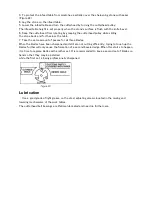
2. Unlock the lock handle (A2) and raise the table to the upright position.
3. Loosen locking nut (C2) with an 18mm wrench.
4. Adjust the table locking shaft (C1) in increments of 1/4 turns or less. Turn clockwise to tighten
the lock handle performance and counterclockwise to loosen.
5. Tighten the locking nut (C2).
6. Test the locking function and repeat if necessary.
Belt Replacement
Disconnect machine from power source before making any adjustments.
Failure to comply may cause serious injury.
Preparation
To replace the cutterhead drive belt and/or the planer feed-roller belt, the jointer fence assembly
and two back panels must first be removed as
described below. A 4mm hex wrench and two 13mm wrenches are required.
1. Remove the jointer fence assembly (A) by first loosening and removing two lock handle
assemblies (B). A 4mm hex wrench is helpful, but not necessary.
Содержание PT260
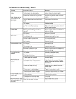
Страница 25: ...Troubleshooting Performance Troubleshooting Jointer ...
Страница 26: ...Performance Troubleshooting Planer ...
Страница 27: ...Mechanical Troubleshooting Planer Jointer ...
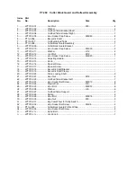
Страница 28: ...PT 260 Cutter Block Guard and Outfeed Assembly ...
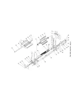
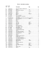
Страница 30: ...PT 260 Cutter Block assembly ...
Страница 32: ...PT 260 Base Assembly ...
Страница 34: ...PT 260 Infeed Table Assembly ...
Страница 36: ...PT 260 Drive and Motor Assembly ...
Страница 38: ...PT 260 Thickness Table Assembly ...
Страница 40: ...PT 260 Working Fence Assembly ...

