background image

12

Safety functions

The machine is equipped with the safety functions de-
scribed as follows.

Electromagnetic brake

The electromagnetic brake (A) is integrated in the front 
wheel's traction system and keeps the machine braked 
when it is turned off  and when it is on but stopped.
The key (A1) locks/releases the brake.
(see chapters: “PUSHING/TOWING THE MACHINE” and 
“ELECTROMAGNETIC BRAKE”.

Traction safety micro-switch

It is installed in the driver's seat in zone (B) and does not 
allow any machine operation if the driver is not seated.

Emergency stop button

It is on the control and commands panel in position (C); it 
is easily accessible by the operator.
It must be pressed fi rmly if urgently required in order to 
stop all machine functions.
Turn it clockwise too release it and restore all machine 
operations.

C

A

B

D

D

A

1

A

1

Anti-tipping tubes

These are two tubes (D) on the right and left front parts 
of the frame that prevent the machine from tipping over.
   

Содержание KILO

Страница 1: ...RCM S p A via Tiraboschi 4 41043 Casinalbo Modena Italy Tel 39 059 515 311 Fax 39 059 510 783 www rcm it info rcm it 5 2015 Rev 00 INSTRUCTION AND MAINTENANCE HANDBOOK EN 33 KI 001 KILO KILO ...

Страница 2: ...2 KILO ...

Страница 3: ... 12 TECHNICAL FEATURES 13 ACCESSORIES AND COMPONENTS UPON REQUEST 14 WIRING DIAGRAM 15 16 PUSHING TOWING THE MACHINE 17 USE 18 BATTERIES 18 Check Installation of the new batteries on a new machine 18 Batteries installation replacement 18 Setting of type of batteries installed 18 PRELIMINARY OPERATIONS BEFORE STARTING THE MACHINE 19 ELECTROMAGNETIC BRAKE 19 BRUSHES 20 Disc brushes only for KILO ver...

Страница 4: ...PERATION 29 Adjustments and checks 29 EMPTYING OF TANKS 30 Emptying of recovery water tank 30 Emptying the detergent solution or washing water tank 30 Emptying 5 litre detergent tank DETERSAVER UPON REQUEST 31 Detergent solution or washing water tank level 32 Recovery water tank level 32 AFTER MACHINE USE 33 LONG DOWNTIME OF MACHINE 33 FIRST PERIOD OF USE 34 MAINTENANCE 34 Planned maintenance tabl...

Страница 5: ...and disconnection of the batteries connector 41 Charging the batteries 42 Charging the batteries for machines without on board battery charger Using external battery charger 42 Charging the batteries for machines with on board battery charger upon request 43 Check Replacement of fuses 44 Disassembly assembly of vacuum motor 45 TROUBLESHOOTING 46 SCRAPPING 47 ...

Страница 6: ...rom failure to observe this prohibition Storage of the manual This manual must be stored next to the machine in the special bag protected from liquids and anything else that may jeopardise readability Declaration of conformity The declaration of conformity supplied with the machine certifies compliance of the machine with the provisions of law in force NOTE The original CE declaration of conformit...

Страница 7: ...itting in the driving position on the operator s seat UNPACKING DELIVERY Carefully follow the instructions on the packaging to unpack the Machine Refer to the Pushing towing the machine paragraph to manually push the machine When the machine is delivered check that the packing and the machine were not damaged during transportation If the damage is evident keep the packing and have it checked by th...

Страница 8: ...nments with dusts liquids or vapours that are harmful danger ous flammable and or explosive This machine is not suitable for collecting dangerous dusts When charging lead batteries WET highly explosive hydrogen gas is produced therefore the opera tion must be carried out only in well ventilated areas that are away from open flames ATTENTION Before performing any maintenance repairs carefully read ...

Страница 9: ...ou tamper with the protections provided for the machine carefully follow the routine maintenance instructions Do not let any object enter the machine s openings Do not use the machine if the openings are blocked keep the machine s openings free from dust lint hair and any other foreign body that may reduce air flow Do not remove or alter the labels affixed by the machine s Manufacturer Release the...

Страница 10: ...ecovery water tank pipe level 20 Detergent tank DETERSAVER upon request 21 Detergent tank cap DETERSAVER upon request Automatic 5 litre tank detergent feeding system DE TERSAVER parts 22 Detergent solution or washing water tank cap 23 Recovery water emptying tube 24 Washing water drain tap 25 Batteries holder case 26 Flashing light upon request 27 Slot for recovery water breakwater protection wall...

Страница 11: ...activating lowering and rotation of the disc brush 13 Luminous indication of the disc brush activated the luminous indicator flashes when switching from deactivat ed to activated and vice versa 14 Button to activate lowering of the squeegee and recovery water suction 15 Luminous indication of the squeegee and suction activated the luminous indicator flashes during switch from deactivated to activa...

Страница 12: ...C BRAKE Traction safety micro switch It is installed in the driver s seat in zone B and does not allow any machine operation if the driver is not seated Emergency stop button It is on the control and commands panel in position C it is easily accessible by the operator It must be pressed firmly if urgently required in order to stop all machine functions Turn it clockwise too release it and restore ...

Страница 13: ...hing capacity 2120 m h Autonomy hours based upon 118 Ah batteries 2 30 Detersaver Upon request Mixing ratio 1 5 Machine body dimensions with squeegee and brush length x height x width 1340 x 1130 x 600 mm Basic weight of the empty machine in operation with 118Ah batteries with tanks empty without operator on board 235 Kg Gross weight of the ready machine with 118Ah batteries with full solution tan...

Страница 14: ...bbers in materials other than standard ones See the chapter regarding Use the diagram for selection of type of squeegee rubbers Front and rear wheels in different materials Automatic detergent feeding system C DETERSAVER based upon 5 Litre tank Breakwater protection wall for the recovery water tank antisplash feature Flashing light E Kit F for filling the tank with detergent solution or washing wa...

Страница 15: ...n K1 Brush contactor K2 Suction contactor K3 Brush release contactor K4 Brush contactor NA contact K5 Suction contactor NA contact K6 Brush release contactor NA contact M Drive motor M3 Chemical detergent pump M4 Water pump M1 Brush actuator M2 Squeegee actuator SP Brush motor ASP Vacuum motor SWC Start up key switch SWG Water float SWM Seat micro switch BR Reverse drive buzzer LAMP Flashing P SPE...

Страница 16: ...16 WIRING DIAGRAM 2 2 ...

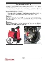
Страница 17: ...ing towing When finished unscrew and remove the key to apply the brakes again and bring the machine back to safe con ditions Store the key in a safe place and within reach in the event the machine has to be moved ATTENTION After having moved the machine and to reactivate the electromagnetic brake A always remember to remove the key A1 Check that the electromagnetic brake is reactivated by pushing ...

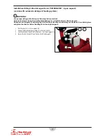
Страница 18: ... the batteries connector and the battery charger s plug Handle the batteries carefully Install the protective caps of the batteries terminals The machine can be supplied in one of the following configurations With batteries WET or GEL or AGM already assembled on the machine and ready for use Batteries not supplied Depending on the type of supply received operate as follows a Batteries WET or GEL o...

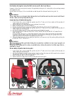
Страница 19: ... back on the brushes base and the squeegee automatically lift ELECTROMAGNETIC BRAKE BRAKING is assisted by the electric brake 1 THE electric brake is integrated in the traction system of the front in wheel electric motor 2 and keeps the machine braked when it is off or when it is on but stopped The electric brake is equipped with a key 3 to unlock and manually move the machine when it is stopped f...

Страница 20: ...ly and only for an instant thereby lowering the hub that will couple the brush If the brush is not coupled climb down from the machine and reposition the brush on the coupling hub which should have remained lowered thereby easing alignment then repeat the operations described in the previous points 5 6 and 7 8 The disc brush A is coupled and ready for use if necessary turn the machine off by rotat...

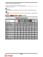
Страница 21: ...t the RCM representative NOTE The table below shows a selection of the most used products For special requirements contact the RCM rep resentative SELECTION TABLE OF TYPE OF DISC BRUSHES Type of disc brush Union Mix Prolite Prolene Aglite Grit 500 MidGrit 240 MidLite Grit 180 Dyna Grit 80 Magna Grit 46 Floors Aggressiveness Light Medium Light Medium Medium Medium Strong Strong Very Strong Aggressi...

Страница 22: ...elerator K lightly and only for an instant thereby lowering the hub that will couple the pad holder driving disc If the pad holder driving disc is not coupled climb down from the machine and reposition the pad holder driving disc on the coupling hub which should have remained lowered thereby easing alignment then repeat the operations described in the previous points 5 6 and 7 8 The pad holder dri...

Страница 23: ...or surface If in doubt contact the RCM representative NOTE The table below shows a selection of the most used products For special requirements contact the RCM rep resentative SELECTION TABLE OF TYPE OF PAD FOR PAD HOLDER DRIVING DISC Type of pad Aggressiveness Light Medium Light Medium Medium Hard Rough Very Rough Crystallis ing Polishing Floors Colour code White Red Blue Green Brown Black Grey B...

Страница 24: ...egee 7 Rotate the squeegee unit inwards towards the machine in a central work position 8 The squeegee A is coupled and ready for use if necessary turn the machine off by rotating the ignition key B to 0 and extract it ATTENTION Use of the machine with the squeegee not perfectly assembled can cause injury to people and damage to equipment Always ensure all components have been assembled before star...

Страница 25: ...OR SQUEEGEE Type of floor Colour of rubbers Polyure thane SH35 Linatex SH35 Natural rubber SH33 Natural rubber SH37 Natural rubber SH40 Floor with fatty oil acids Quartz concrete floor rough floor and floor without joints without joints between the tiles Floor with joints with joints be tween the tiles very thorough drying of the floor Floor with joints with joints be tween the tiles average dryin...

Страница 26: ...Use a proper detergent for the type of cleaning to be carried out Only use low foam and non flammable liquid detergents suitable for the machine to be used During use of detergents for cleaning floors follow the instructions and warnings on the labels Use suitable gloves and protective devices before handling floor cleaning detergents Inlet in basic version 1 Unscrew the cap D and pour water in th...

Страница 27: ...tergents suitable for the machine to be used During use of detergents for cleaning floors follow the instructions and warnings on the labels Use suitable gloves and protective devices before handling floor cleaning detergents 1 Put the tank 1 in its support 2 2 Connect the detergent pump tube 3 to the tank s lid 4 3 Use the elastic strap 5 to fix the tank 1 to the support 2 4 Open the lid 4 and fi...

Страница 28: ...ge E and relative graphic F Charge the batteries if necessary see the procedure in the Maintenance chapter ATTENTION The machine is not suitable for use on uneven floors 5 Go to the work area by starting the machine with your hands on the steering wheel and pressing the pedal G The forward speed is adjustable from zero to its maximum set value based on the pressure exerted on the pedal G 6 To acti...

Страница 29: ... the previous chapter 2 If necessary adjust the balance of the squeegee T see the procedure in the Maintenance chapter 3 If required use buttons I to alter the flow of the detergent solution or washing water 4 Upon request If required use buttons J to alter the percentage of the washing detergent 5 If required press the turbo button R to activate maximum flow of detergent solution 6 If required us...

Страница 30: ...ssary wash the recovery water from the tank H see the procedure in the Maintenance chapter 7 Tighten the cap D and engage the tube A in the relative seat of the machine Emptying the detergent solution or washing water tank 1 Take the machine to the intended area for disposal of the detergent solution or washing water in compliance with the emission standards in force 2 Rotate the machine s ignitio...

Страница 31: ...the elastic strap 5 3 Remove the tank 1 from its support 2 4 Open the cap 4 and empty the tank in the area designed for this purpose 5 Clean the tube 3 and the parts of the detergent feeding system only in the event of prolonged in activity of the machine 6 Place back the tank by following the steps above in reverse order 1 2 3 4 5 ...

Страница 32: ...ve tank is visible through the transparent tube A the side indications B define the amount Recovery water tank level When the recovery water tank is full the float C stops water suction empty the tank to continue suction See the procedure on emptying the re covery water tank in the Emptying of tanks par agraph A B C ...

Страница 33: ...used for more than 30 days you must 1 Follow what is indicated in the After machine use paragraph 2 Clean the detergent feeding system DETERSAVER upon request as described in the Emptying the 5 Litre detergent tank section 3 Disconnect the connector of the batteries as described below extract the left pin A then rotate it a half turn to lock it in the extracted position extract the right pin B and...

Страница 34: ...res are described in this manual after the planned mainte nance table NOTE For the procedures of the other maintenance operations foreseen in the planned maintenance table and for the other repair procedures contact the authorized technical service centre PLANNED MAINTENANCE TABLE Operation Daily after machine use Monthly or every 100 hours Twice yearly or every 400 hours Yearly or every 800 hours...

Страница 35: ...or to be well dried WARNING It is advisable to use protective gloves when cleaning the squeegee since there can be sharp debris 1 Disassemble the squeegee if necessary See procedure in the specific paragraph 2 Wash and clean the squeegee D clean the compartments E and the recovery water passage hole F from dirt and debris Check that the front rubber G and the rear rubber H are intact and have no c...

Страница 36: ...d open the eccentric E then disengage it from the hook I 2 Loosen the terminal nuts F 3 Remove the retaining strip G by disengaging it from the pin nuts F and from the pins H 4 Remove the terminal strip J 5 Replace or reverse the rear rubber B then reassemble the removed parts operating in reverse order to re moval Replacement of front squeegee rubber 1 Unscrew the self locking nuts K on the insid...

Страница 37: ...eel on the other side of the machine Cleaning the disc brush WARNING It is advisable to use protective gloves when cleaning the disc brush because there can be cutting debris 1 Disassemble the disc brush if necessary See procedure in the specific paragraph 2 Wash and clean the disc brush D from dirt and debris 3 Reassemble the disc brush if disassembled See procedure in the specific paragraph 4 Th...

Страница 38: ...the entire perimeter gasket J Check that the perimeter gasket J is intact if it is damaged it may compromise correct operation of the recov ery water suction WARNING Do not damage the float K 5 Extract the recovery water inlet L from its seat and wash it then put it back in its seat 6 Extract the suction inlet M from its seat and clean and wash it also clean its drain hole N from dirt Be careful t...

Страница 39: ...tergent solution or washing water filter 1 With the machine s controls lower the squeegee and the disc brush then turn the ignition key to 0 and ex tract it see Use chapter 2 Operate on the right side of the machine to unscrew and remove the transparent cover with filter D 3 Remove the filter E from the transparent cover F 4 Clean the filter E and the transparent cover F 5 Replace the filter E in ...

Страница 40: ...ling hub A of the brush unscrew the ring nut B and recover the nozzle C and the gasket D 3 Clean the nozzle C 4 Place the nozzle C and the gasket D in their seat and then screw the ring nut B 5 Reassemble the brush See procedure in the specific paragraph ATTENTION Appropriately protect body parts eyes hair hands etc when cleaning with compressed air or water guns B C A E B E C F D G ...

Страница 41: ...on 3 Extract the right pin B and keep it in the extracted position 4 Use the handle C to completely extract the batteries holder case D then engage the pin B on the relative locking hole of the batteries case 5 Disconnect the connector E of the batteries Proceed as follows for connection and closure of the case 1 Reconnect the connector E of the batteries 2 Disengage the pin B and carefully put th...

Страница 42: ...oard battery charger Using an external battery charger 1 Take the machine to a suitable area to charge the batteries 2 Open the batteries holder case and disconnect the batteries connector see procedure in the previous para graph 3 Only for lead batteries WET check the correct level of the electrolyte inside the batteries E restore it through the cap F if necessary leave all caps F open for subseq...

Страница 43: ...he connector G to the electrical mains after having checked that the mains nominal volt age is the one foreseen for charging the machine Refer to the machine s technical data plate The batteries start charging NOTE When the battery charger is connected to the mains all machine functions are automatically excluded 5 Charging is complete when 100 is shown on the zone H of the display and the notches...

Страница 44: ...from its lower pins H 3 Check replace the fuse 10A fuse for auxiliary services I protection ATTENTION Request intervention of a qualified technician or of the Service Centre for replacement of the other fuses 4 Insert the panel G by engaging it in its lower pins H 5 Screw back the screw F 6 Extract the batteries case again and connect the batteries connector 7 Connect the batteries connector and c...

Страница 45: ...ed platform otherwise place it on a level floor 2 With the machine s controls as foreseen in the Use chapter lower the brush and the squeegee then rotate the ignition key to 0 and extract it 3 Open the batteries holder case and disconnect the batteries connector see procedure in the previous para graph 4 Operate on the left side of the machine to unscrew the screws A 5 After having disconnected th...

Страница 46: ...let nozzle dirty Clean nozzle Detergent solution or washing wa ter tank dirty Clean the tank No flow of detergent solution or washing water to the disc brush Detergent solution or washing wa ter tank empty Fill the tank Detergent solution E page 42 or washing water filter clogged Clean the filter Detergent solution or washing wa ter outlet nozzle clogged Clean the nozzle Insufficient no flow of wa...

Страница 47: ... recycle it responsibly to promote the sustainable reuse of material resources Scrap this machine at an authorised demolition company Before scrapping the machine remove and separate the following materials and send them to a waste collection centre in compliance with the environmental health standards in force Batteries Disc brush Tubes and parts in plastic Electrical and electronic parts Especia...

Отзывы: