THE PVCore 3D PRINTER
12/28/2016
BY RCJOSEB
PAGE 62 OF 107
GT2 MOTOR PULLEY AND BELTS – INSTALLATION:
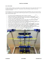
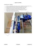
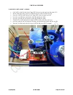
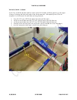
As with most CoreXY printers, the PVCore utilizes two belts for the X/Y axis motion, with one belt placed above the other one.
The upper GT2 belt (GT2-5):
Is indicated by the yellow arrow.
Starts at the front right corner of the X axis slide.
Goes around the right Y slide’s upper bearing.
Goes around the right bearing mount’s upper bearing.
Goes around the left bearing mount’s upper bearing.
Goes around the left motor’s motor pulley.
Goes around the left Y slide’s upper bearing.
Stops at the left rear corner of the X axis slide.
The lower GT2 belt (GT2-5):
Is indicated by the red arrow.
Starts at the rear right corner of the X axis slide.
Goes around the right Y slide’s lower bearing.
Goes around the right motor’s motor pulley.
Goes around the right bearing mount’s lower bearing.
Goes around the left bearing mount’s lower bearing.
Goes around the left Y slide’s lower bearing.
Stops at the left front corner of the X axis slide.
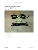
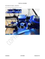
Place the motor pulleys (MP) onto the motors but do not tighten the set screws.
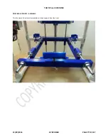
Prevent the X Axis slide from moving away from the right front corner of the PVCore by using either tape or string.
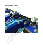
Start with the upper belt first with the belt’s teeth facing away from you.
Wrap the GT2 belt around the screw on the X Axis slide once so the teeth face each other.
Use a small zip tie to hold the GT2 belt onto the screw on the X Axis slide.
Run the GT2 belt around the PVCore.
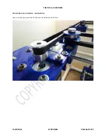
Pull on the GT2 belt so that it remains taught while you attach the end to the other screw on the X Axis slide.
Use a small zip tie to hold the GT2 belt onto the screw on the X Axis slide.
Run the lower GT2 belt using zip ties as before and with the belt’s teeth facing away from you.
Lower/raise the motor pulleys so that the GT2 belts are level horizontally.
Screw in the motor pulley (MP) set screws using Blue Loctite.

