THE PVCore 3D PRINTER
12/28/2016
BY RCJOSEB
PAGE 58 OF 107
Y AXIS INSTALLATION:
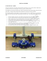
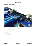
When installing the Y axis, keep the bearing mount on the side of the smooth rod (S5MM) that is farther away from the PVC
frame. It may be necessary to cut the 6mm smooth rod (S6mm), depending on how well you cut the PVC frame. I had to
shorten my smooth rods by about 0.25”.
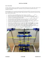
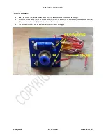
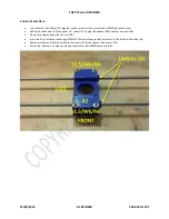
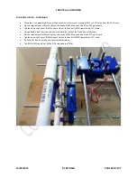
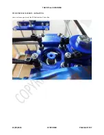
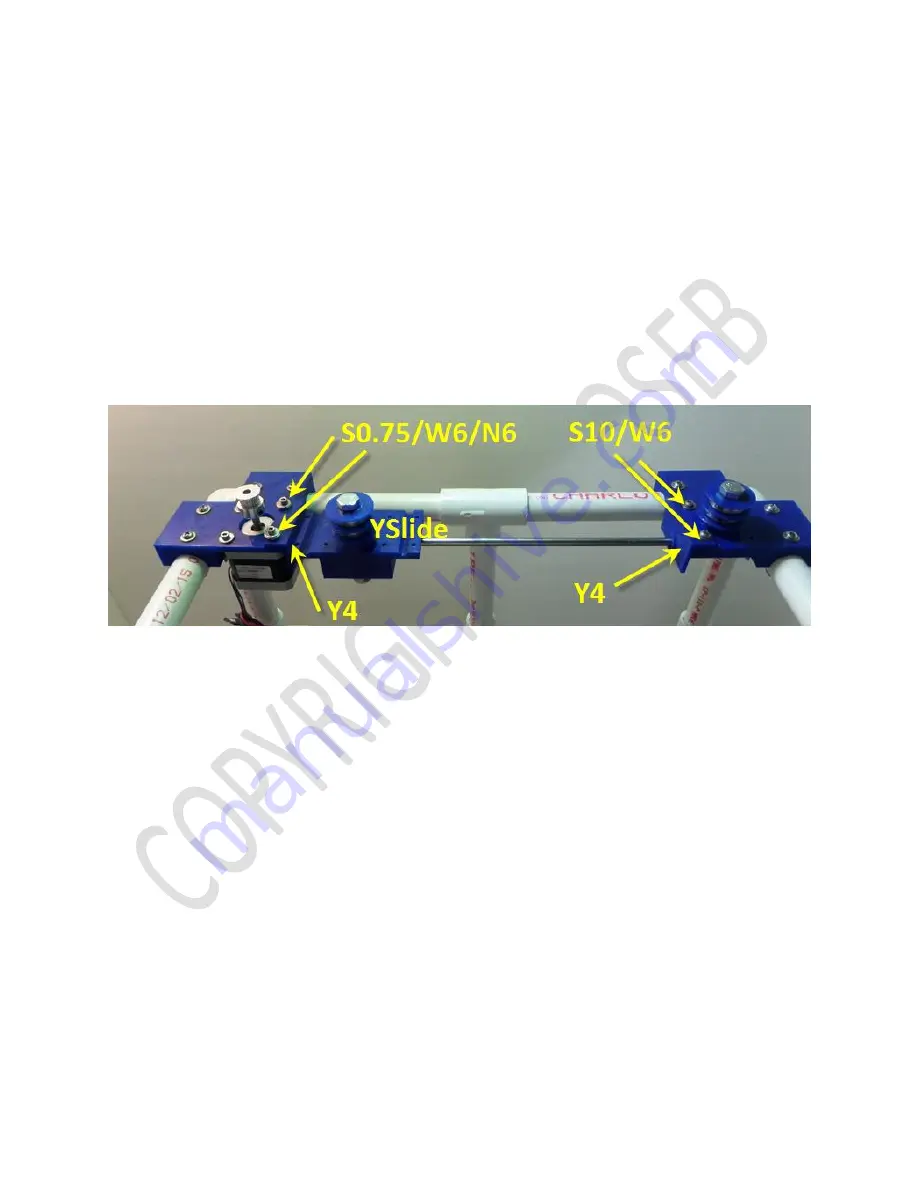
Remove the two front existing M3 x 5mm cap head screws as indicated by the yellow arrows.
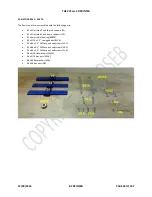
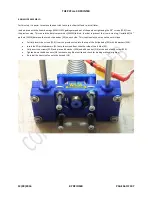
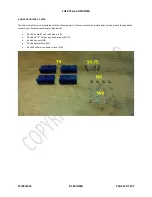
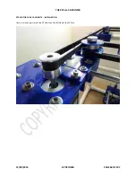
Place a Y rod holder (Y4) on each end of a 6mm smooth rod (S6MM) that is being used for the Y axis.
Place the front Y rod holder (Y4) onto the motor mount (M1).
Place the rear Y rod holder (Y4) onto the bearing mount (B1).
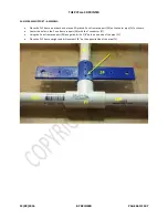
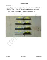
Replace the M3 x 5mm (S5) screws with M3 x 10mm cap head screws (S10) and three #6 washers (W6).
Insert the # 6 x 0.75” screws (S0.75), #6 washers (W6) and #6 hex nuts (N6) on the rear Y rod holder (Y4).
Place a dab of Blue Loctite on the screws (S0.75) and tighten the #6 hex nuts (N6).
Repeat the above steps for the other side.
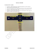
For the next step, remove or loosen the blocks (Y3) that were previously installed on the Y slide (Y1/2).

