THE PVCore 3D PRINTER
12/28/2016
BY RCJOSEB
PAGE 68 OF 107
Y AXIS ENDSTOP SWITCH MOUNT – INSTALLATION:
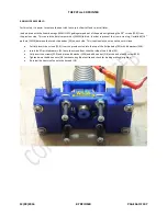
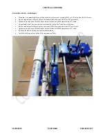
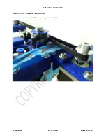
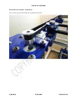
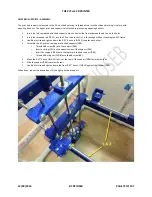
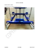
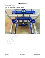
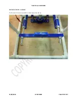
The picture shows the assembled Y Axis Endstop Switch and where it needs to be placed along the Y Axis rod (S6MM). The
switch on the endstop is triggered when the X Axis slide is about 1mm to mm away from the motor mounts. If the switch is not
triggered, adjust the position of the endstop.
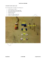
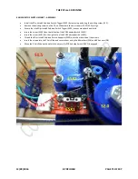
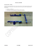
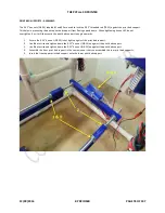
Place the 3D printed Y Axis Endstop Switch Mount (ESY3) onto the right Y Axis smooth rod (S6MM) as shown.
Place the 1/8” foam (ESY2) underneath the mount and use a scissor to poke holes through the foam.
Place the PCB Endstop Switch (ESY1) underneath the foam (ESY2) and align the holes.
Use the 4” zip ties to hold the three parts together. Ensure the heads on the zip ties are below the endstop.
Place another 4” zip tie around all three parts to ensure a strong hold.
Use a 6” zip tie to hold the endstop cables to the PVCore.
Test the switch by moving the X Axis slide along the Y Axis.

