30
Cast Iron Condensing Boilers – Installation Manual
FlexCore Stainless Steel Condensing Boilers – Installation Manual
18. Remove the demand from the 7800 control by
disabling the low fire switch allowing the boiler to stop.
19. Close manual main shut-off valve 2 and the pilot gas
shut-off valve, Figure 17. Connect both sides of a
manometer or pressure gauge to the manometer
pressure taps (differential pressure barbed
connections) on the pressure test manifold located
inside the upper control panel. Add additional
manometers to the set of pressure taps provided for
the middle and rear modules on units (CK3500
-CK9000). (See Figure 21).
20. Switch the Honeywell 7800 back to "run".
21. Create a minimum input demand as before (enable
the low fire switch on the HeatNet board). The boiler
will begin the start sequence. For units (CK3500 -
CK9000), the low fire switch on the Manager
HeatNet Board will enable all the additional
modules.
22. Monitor the flame current on the 7800. No flame
current should be detected and the 7800 should
lock out. If flame current is detected at any time up
to the 7800 locking out, the 120V wiring on the
ignition transformer must be reversed and the test
run again to insure that no flame is detected.
Improper wiring of the ignition transformer
can result in an explosion causing extensive
property damage, severe personal injury or
death!
23. Open both manual main shut-off valves and the pilot
gas shut-off valve.
24. Reset the Honeywell 7800. The boiler will start and
will run at minimum input rate.
25. Setting the Min VFD and Low Fire Combustion
values: The boiler will cycle and achieve low fire
status. Allow low fire to settle out for a few minutes
and observe the combustion reading.
The Calibration (Min % & Max %) represents
the mapped signal sent to the blower
and doesn’t reflect the (modulation %) as
indicated on the Master/Member Screens.
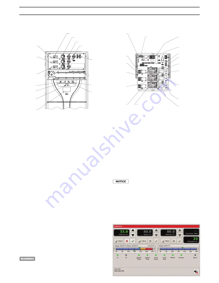
a. Place the ‘S2’ - Calibration switch located on the
3.0 HeatNet board to the ‘CAL’ position. A reloading
message will be displayed and then the calibrate
screen. Follow the same procedure for the middle
and rear modules on units (CK3500 - CK9000).
AIR PUMP
TOUCH SCREEN
LOW WATER
CUTOFF
USB
POWER SWITCH
CABINET LIGHT
(CK0850 TO 9000)
FRONT MODULE
BLOWER PROVE
BLOCKED FLUE
BLOCKED INLET
PRESSURE TAPS
(CK3500 TO 6000)
REAR MODULE
OR
(CK7000 TO 9000)
CENTER MODULE
(CK7000 TO 9000)
REAR MODULE
LOCAL / REMOTE
SWITCH
RIOM-0212_C
RIOM-0212_C
(CK3500 TO 6000)
MEMBER HEAT-NET
CONTROL BOARD
REAR MODULE
OR
(CK7000 TO 9000)
MEMBER HEAT-NET
CONTROL BOARD
CENTER MODULE
(CK3500 TO 6000)
FLAME SAFEGUARD
REAR MODULE
OR
(CK7000 TO 9000)
FLAME SAFEGUARD
CENTER MODULE
(CK0850 TO 9000)
HIGH LIMIT
MANUAL RESET
(CK3500 TO 6000)
AUTO HIGH LIMIT
REAR MODULE
OR
(CK7000 TO 9000)
AUTO HIGH LIMIT
CENTER MODULE
(CK2500 TO 9000)
AUTO HIGH LIMIT
FRONT MODULE
(CK0850 TO 6000)
12V - 5A POWER SUPPLY
OR
(CK7000 TO 9000)
12V - 8.5A POWER SUPPLY
(CK3500 TO 6000)
BLOWER RELAY
REAR MODULE
OR
(CK7000 TO 9000)
BLOWER RELAY
CENTER MODULE
(CK7000 TO 9000)
BLOWER RELAY
REAR MODULE
POWER SUPPLY
CONNECTIONS
PUMP STARTER
(CK7000 TO 9000)
MEMBER HEAT-NET
CONTROL BOARD
REAR MODULE
(CK0850 TO 9000)
MANAGER HEAT-NET
CONTROL BOARD
FRONT MODULE
(CK0850 TO 9000)
BLOWER RELAY
FRONT MODULE
(CK0850 TO 2000)
50 VA TRANSFORMER
OR
(CK1500 TO 2000)
250 VA TRANSFORMER
OPTION
OR
(CK2500 TO 3000)
250 VA TRANSFORMER
OR
(CK3500 TO 6000)
500 VA TRANSFORMER
(CK7000 TO 9000)
AUTO HIGH LIMIT
REAR MODULE
(CK0850 TO 9000)
FLAME SAFEGUARD
FRONT MODULE
(CK7000 TO 9000)
FLAME SAFEGUARD
REAR MODULE
Figure 18 - Control Panel Components


