RBC Bioscience MagCore HF16Plus Скачать руководство пользователя страница 28

27

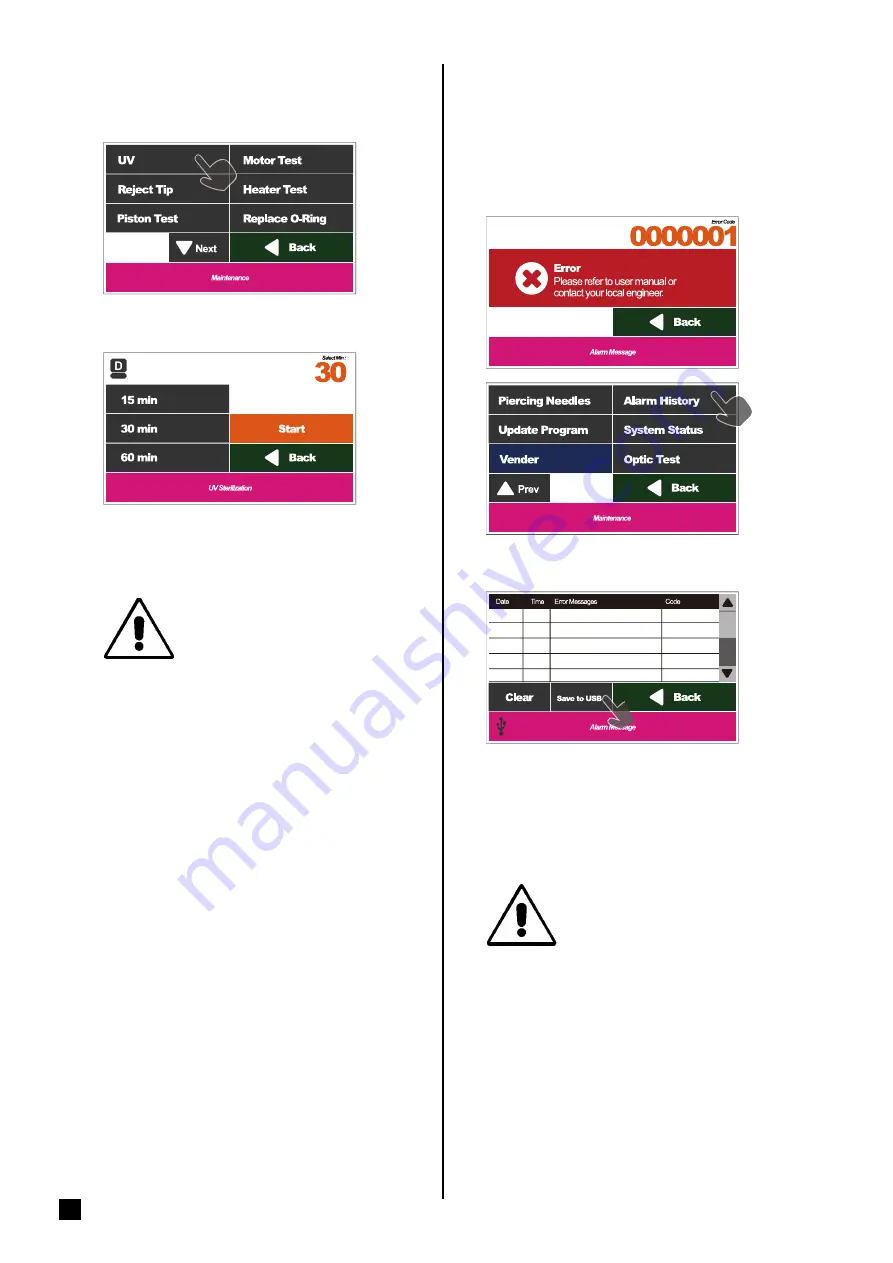
If the machine is not functioning properly or if the 

following messages appears, the engineers may 

ask you to download the error records for them to 

diagnose the machine.

Please select Alarm History.

Save files

Insert the USB Flash Drive and then press the Save 

button to store the current data after the USB icon 

shows in the status bar.  Please take out the USB 

Flash Drive and you can perform other operations 

after the icon of USB Flash Drive disappears.

━ Alarm History

Please save the data in the USB Flash Drive 

and transfer to computer, or the data in 

the USB Flash Drive may be overwritten 

later.

File name: AlarmHistory.cvs

━ UV sterilization       

Please select the UV button.

Please select the sterilization time.

Warning!

The UV lamp is dangerous.  

Please do not look straight into 

the machine during operation.

Содержание MagCore HF16Plus

Страница 1: ...Ver 2020 09 10 04 ...

Страница 2: ...ed on the marking label If you arenot sure of thetype of power supply at your lab consult the seller or local power company For products intended to operate from battery power orothersources refertotheoperatinginstructions 11 Grounding or Polarization Thisproductmaybe equipped with a polarized alternating currentlineplug Thisplugwillfitintothepoweroutletinonewayonly Thisisasafetyfeature Ifyouareun...

Страница 3: ...50 60Hz Dimension W760xD710xH770 mm W27 95xD29 92xH30 31 inches NetWeight 76 5kg 168 68LB MagCoreSuper 68 5kg 151LB MagCoreHF16Plus Specification Operating Parameters Operating Environment Applications Applications Applications Whole Blood DNA 200µl 400µl 1 200µl Viral Nucleic Acid DNA RNA 200µl 400µl 1 200µl FFPE Genomic DNA Forensic DNA Plasma and Circulating Cell Free DNA 1 200µl Tissue Genomic...

Страница 4: ...tcartridge 16 EmergencyStop 17 StartPrograms 18 Ifthe testresultoftheopticmeasurementisoverdetection 19 Stop 21 Enable thebarcodefunction 21 Barcodescanningandediting 22 Optic data 22 Easymaintenance 23 ReplaceO Ring 23 PistonTest 23 Clean PiercingNeedles 25 RejectTip 25 Heater Test 26 Optic Test 26 UVsterilization 27 AlarmHistory 27 SystemStatus 28 Update Program 29 Clean theWasteBox 29 Replaceth...

Страница 5: ...or ofthebase 57 Replace PCB 58 Replace PLC 59 Replace PowerSupply 60 Replace Touch Panel 61 Replace Printer 62 Electricalcontrolandengineeringsoftware 63 System 64 Parts 65 Mainboardconfiguration 66 PLCconfiguration 67 Copy theengineeringsoftwareto thedesktop 68 Installthe HMI updating software 68 Create anuploadingfolder 69 Installthe driver 70 HMIupdating 72 PLCupdating 73 Position TeachingTools...

Страница 6: ... O Rings X 16 7 EmptyCartridge X10 8 SampleTube Elution TubeX 20 9 PipetteTip X 20 10 MagCoreCuvetteSet 10pcs X 1 11 Waste BoxX1 12 BarcodeScannerX1 MagCoreSuperOnly 1 2 3 4 5 7 6 8 9 10 11 12 You can purchase Cat No MSC100 MagCore Cuvette Set X100 from the local distributor MagCore Super Only MagCore HF16 Optional Specification ...

Страница 7: ...6 RBCBioscience BeforeInstallation Installation Please refer to the machine size shown in the above figure to prepare an appropriate position for the machineand reserve spaceforheat dissipation ...

Страница 8: ...7 IQ Documents IQ OQ PQ Documents ...

Страница 9: ...8 RBCBioscience OQ Documents ...

Страница 10: ...9 PQ Documents ...

Страница 11: ...10 RBCBioscience System Overview Slots There area total of16slots number1 16 fromleft to right 1 234 56 789 10 11 12131415 16 ...

Страница 12: ...11 ModulePositionDescription Liquid handling module Work platform Heating module Optic module Super Only Frame Gantry structure ...

Страница 13: ...12 RBCBioscience Unpacking PrepareUnpackingTools Ifthecargoisdamaged White Red Ifthecargoisupsidedown Sliver Red 2 PhillipsScrewdriver 1 HexWrench 3mm 3 Scissors ...

Страница 14: ...e HF16 Plus Super Proceedinstallationproceduresafterplacingtheinstrumentonasolidbench top 1 Usescrewdriverstoloosenthescrewsasshowninthepicture 2 Removetheredfixingplates 3 Saveallthematerialsformaintenanceforfutureuse ...

Страница 15: ...apterforthe informationabouttheoperation PleaserefertoP 23 Step3 Testheater PleaserefertoHeaterTestchapterforthe informationabouttheoperation PleaserefertoP 26 Step4 Testopticmodule MagCore SuperOnly PleaserefertoOpticTestchapterforthe informationabouttheoperation Whentheopticmoduletestisfinished please comparetheresultwiththereferencesheet tomakesuretheopticmoduleisfunctioning properly Pleaserefe...

Страница 16: ...atus ending time andtest report of the machine Theabovefigureshows the function listof theoperation screen and the description ofthestatusicons Start Barcode Maintenance Optics Executethe extractionprocess Easymaintenanceand systemsettings Opticsdatabrowsingand outputfunctions MagCoreSuperonly Barcodescanning editing printing functions optionalforMagCoreHF16 Plus ...

Страница 17: ...isunidirectional Itisnotpossibleto putitintothewellifthedirectionisnotcorrect 2 Putthe200μlSPtipintotheW4oftheT Rack Pleaseinsertthefrontendofthecartridgeintothespace belowthefixingplateoftheCartridgeRack 1 Putthetipintothecorrespondingwellaccordingtotheleft figure 2 PuttheT Rackintothemachine PleaseinstalltheTipandTube accordingtotheinstructionsonthe extractionkitusermanual PleaseinserttheCartrid...

Страница 18: ...security information to correctly stop the machine whenanaccidenttakesplace When an emergency situation occurs and the machine is still running please press the stop button or open the door of the machine to stop themachineimmediately ...

Страница 19: ... instructionsontheMagCore extractionkituser manualandputconsumablesintothemachine PressStarttogotothenextstep Systemwillaskyouwhetherornottoscanthe barcode Ifthereisabarcoderecordfromprevioustest processes thesystemwillaskyouwhetherornot todeletethepreviousbarcoderecord Ifthereis nobarcoderecord thesystemwillnotaskyou MagCoreSuperonly optionalforHF16Plus Start Programs Thenumbercanbe foundinthesti...

Страница 20: ...rtotheopticdatachapter f A Pleaserecordandsavethe currentmeasureddata PleaseselectYES Pleasecheckthevalueofeachsample If thereisavalueshowingDNA 300ng μlorRNA 240ng μl pleaserecord thenumberofthesample Itmeansthe sampleneedstobediluted Afterrecording thenumberoftheslot pleaseinsertthe USBFlashDriveandpresstheSavebutton tosavetocurrentmeasureddata After finishingtheabovesteps pleasepressNext Step 1...

Страница 21: ... values 1 InserttheUSBFlashDriveandthen presstheSavebuttontosavethe currentmeasuredvaluesaftertheUSB iconshowsinthestatusbar Please takeouttheUSBFlashDriveand youcanperformotheroperations aftertheiconofUSBFlashDrive disappears 2 Thefilesavedlasttimeandthistime willbekeptinthemachine Ifthefilesavedlasttimeislost you canretrievethisfileaccordingtothe instructionsinoptictestdatachapter Pleasesavethed...

Страница 22: ...r TheBarcodefunctionisenabled Enablethebarcodefunction 1 2 3 MagCoreHF16PlusOnly Duringthetestprocess pleasepresstheStop buttonifyouwanttopause PleasepresstheAbortbuttonifyouwanttoend thetest Thetestisaborting andthemachineisreturning totheinitialposition Pleasedonotoperatethe machineduringtheprocess Themachinehasbeenstoppedandreset please presstheOKbuttontogobacktothemainmenu Stop 1 2 3 4 ...

Страница 23: ...tabuttoninthemain menu OpticsDatamainmenu Themachinewillautomaticallysavetwobatchesof datainthememory Savefile InserttheUSBFlashDriveandthenpressthe Savebuttontostorethecurrentmeasured valuesaftertheUSBiconshowsinthestatus bar PleasetakeouttheUSBFlashDriveand youcanperformotheroperationsafterthe iconofUSBFlashDrivedisappears PleaserefertotheSystemOverviewchapterforthe informationaboutthenumbersoft...

Страница 24: ...piston is smooth attakingallthreetypesoftipsfromtheT rack PleaseselectthePistonTestbutton ReplaceO Ring Piston Test Easymaintenance 2 1 Easymaintenanceincludesthemaintenances whichneedtobedonebyusers Theseitems includesterilization clearing simpletestanderror messagereport etc Usersmustperformthese itemsperiodicallytoensurethesystemisfunctioning properly Maintenance Please perform the Piston Test ...

Страница 25: ...leaseadd1mlwatertotheSampleTube andputitinW1oftheT Rack 3 PleaseselectTestW3Tip 4 Pleasecheckwhethertheliquidlevelsare consistentwitheachother Iftheliquidlevels arenotconsistentwitheachother please checktheO Ring PleaserefertotheReplaceO Ring chapterformoreinformation C TesttheTipoftheW4 MagCoreSuperOnly 1 Pleaseputthe200μlSPTipintoW4ofT Rack 2 Pleaseadd1mlwatertotheSampleTube andputitinW1oftheT R...

Страница 26: ...ecloth If the system is stopped from power shortage or other abnormal conditions and the tips are still on the pistons you haveto press RejectTip to remove thetipsfromthepistons PleaseselecttheRejectTipbutton Clean Piercing Needles 2 1 1 Warning ThetipsofthePiercingNeedles areextremelysharp Please cleanthemcarefully ...

Страница 27: ...totheInstallMagCore Cuvette chapter PleaseselectOpticTest PleaseselecttheEmptyCuvetteandthenwaitfor 15minutestoperformthetest Thetestmaytakesometimetowaitforthe D2lamptoprewarm Thescreenwillshowthe measuredvaluesafterthetestisfinished You caninserttheUSBFlashDriveandpresstheSave buttontostorethecurrentdataaftertheUSBicon showsinthestatusbar PleasetakeouttheUSB FlashDriveandyoucanperformotheroperat...

Страница 28: ...taaftertheUSBicon showsinthestatusbar PleasetakeouttheUSB FlashDriveandyoucanperformotheroperations aftertheiconofUSBFlashDrivedisappears Alarm History PleasesavethedataintheUSBFlashDrive andtransfertocomputer orthedatain theUSBFlashDrivemaybeoverwritten later Filename AlarmHistory cvs UV sterilization PleaseselecttheUVbutton Pleaseselectthesterilizationtime Warning The UV lamp is dangerous Please...

Страница 29: ... Serial Optical module serial number MagCore Super Only Power on Time The total time that the machine is powered on UV Lamp Used Time The used time of the UV lamp D2 Lamp Used Time The used time of the D2 lamp MagCore Super Only SelectSystemTimeSetuptosetupthesystem timeofthemachine Setupthesystemtime Pleaseinputthelocaldateandtime thenpressthe Updatebuttontosave Youcanseethetimethat youchangedin ...

Страница 30: ...FlashDriveintotheUSBPortofthe machine Pleasepress UpdateProgram after theUSBiconappearsinthestatuslist PleaseselectYES Theupdateisfinished pleasepressOKtocheck whethertheUIversioniscorrect Pleaseremovethewastewhentheprogramis completedandwashthewasteboxeveryday Warning Pleaseconfirmthenameof UIversion Iftheversionisnot correct pleaseexecutethe updateprogramagain ...

Страница 31: ... figureandthenclosethecoveroftheprinter If the position of the thermal paper roll is not correct thered yellow lamp will flash Pleasepress the Feed button to confirm if the replacement is correctlydone Replacethermalpaper Replacefuse 250V5A Please use the specific fuse If you usethefusewithhigherspecification themachinemaybeburned You can purchase the Cat No MSP005 Thermal Paper from the local dis...

Страница 32: ...advanced machine calibration Only trained engineers can perform the above operations Advanced maintenance Recommended frequency for maintenance Frequency of use Maintenance cycle Less than 20 times a month 1 Year 1 to 3 times daily Six months More than 3 times a day Three months ...

Страница 33: ...32 RBCBioscience Turnoffthepowerandremovepowersocket beforeprocessingadvancedmaintenance Caution Caution Alladvancedmaintanencemustbeperformed bytrainedEngineers ...

Страница 34: ...33 Disassemblethebackservice lid ...

Страница 35: ...34 RBCBioscience Disassemblethetopservicelid ...

Страница 36: ...35 Axisdirections V axis direction X axis direction Y axis direction C axis direction M axis direction ...

Страница 37: ...ience ReplacetheUVlamp Open the front door 1 Switch off the power supply 2 Loosen the three screws of the protection metal sheet 4mm Hex wrench and take off the sheet 3 Replace the lamp and lock back all the parts ...

Страница 38: ...en the front door 1 Unplug the wire connector of the LED 2 Loosen the three or five screws on the top of the piston module 3 mm Hex wrench and take off the LED module 3 Replace the LED light bar and lock back all the parts ...

Страница 39: ...r 1 Loosen four screws of back service lid 2 Loosen four screws of optic service lid 2 Cut cable tie 6 places 3 Loosen three screws 4 Move the deuterium lamp to the right side 1 Open the back service lid 2 Loosen four screws on optic service lid MagCore SuperOnly ...

Страница 40: ...e tray is exposed Use tools to remove connecting part on top of the tray until it is completely opened and cables can be easily removed Hold the base of the tray and twist it to the side to remove it Repeat on the other end of the tray 4 Disconnect the cables 5 Remove 4 screws if needed remove the motor to create more space for operation 6 Remove old power supply 7 Follow the steps in the reversed...

Страница 41: ...e connector of the LED 2 Loosen the three screws on the top of piston module 3mm Hex wrench and take off the LED module 3 Screw off the eight screws on the acrylic nameplate at the front side 2 5mm Hex wrench 4 Screw off the four screws on the metal sheet 2 5mm Hex wrench ...

Страница 42: ...ult pistons and replace with new pistons 2 5mm Hex wrench 8 Screw up the four screws 2 5mm Hex wrench 9 Screw up the screws above the piston 2 5mm Hex wrench 10 Reinstall the acrylic nameplate on the piston module and the LED lamp on the machine 11 After the above steps are finished please perform the Piston Test to check if the replacement is successful ...

Страница 43: ... off the eight screws on the acrylic nameplate at the front side 3mm Hex wrench and take off the LED module 4 Screw off the four screws of the metal sheet 2 5mm Hex wrench 5 Screw off the three screws of the axle core of the ejector rod 2 5mm Hex wrench 6 Take out the ejector rods by pushing it downward 7 Replace the ejector rods and reinstall the ejector rod module back in order ...

Страница 44: ...w off the four screws on the heating module 2 mm Hex wrench 2 Pull out the temperature probe from the module 3 Remove the connection wire to the heater 4 Remove the protection switch wire to the heater 5 Take out the heating module from the bottom 6 Install a new heating module and lock back all the parts ...

Страница 45: ...efront door 1 Open the front door 2 Screw off one screw and one nut 4mm Hex wrench Note that you can only replace one gas spring at a time 3 Screw off the screw on the front door 3mm Hex wrench 4 Replace the gas spring and screw up the screws ...

Страница 46: ...45 ReplaceDoor Sensor 1 Open the front door 2 Pull out the sensor 3 Disconnect the connector ...

Страница 47: ...xissensors Open the front door and take out the waste box cartridge rack and T rack 1 Screw off the two screws on each sensor 2 5mm Hex wrench 2 Remove the wires connected to the sensors 3 Replace new sensors and screw up the screws ...

Страница 48: ...47 Replacethesensorsof C V XandY axes 1 Remove the wires connected to the sensors 2 Screw off the two screws on each sensor 2 5mm Hex wrench 3 Replace the sensors and lock back all the parts V X Y C ...

Страница 49: ...48 RBCBioscience ReplaceCoolingFans 3 Loosen two screws and remove protecting net ...

Страница 50: ... to the X axis motor 2 Screw off the two screws on the holder of the motor 5mm Hex wrench 3 Screw off the two screws on the timing gear 1 5mm Hex wrench 4 Screw off the four screws on the motor 3mm Hex wrench 5 Replace the X axis motor 6 Install the new X axis motor on the machine ...

Страница 51: ... four screws on the metal sheet of the Y axis motor 3mm Hex wrench 4 Screw off the two set screws on the timing gear 2 mm Hex wrench 5 Screw off the four screws on the motor 3mm Hex wrench 6 Replace the Y axis motor 7 Install the new Y axis motor on the machine 8 Note that the belt should have always some tension when reinstalling it 9 Disassemble the Y axis fixing plate and screw off the two scre...

Страница 52: ... 2 Screw off the four screws of the metal sheet of the Y axis motor 3mm Hex wrench 3 Push the metal sheet of the motor forward 4 Replace the timing belt 5 Install the Y axis motor on the machine 6 Note that the belt should be a little tight when reinstalling it 7 Disassemble the Y axis fixing plate and screw off the two screws Phillips screwdriver ...

Страница 53: ...nnector of the LED 2 Loosen the three screws on the top of piston module 2 5mm Hex wrench and take off the LED module 3 Screw off the eight screws on the acrylic nameplate at the front side 2 5mm Hex wrench 4 Screw off the four screws on the reinforced metal sheet 1 5mm Hex wrench ...

Страница 54: ...ion wire to the V axis motor 6 Screw off the four screws on the motor 3mm Hex wrench 7 Screw off the three screws on the axle sleeve 2 5mm Hex wrench 8 Replace a new V axis motor 9 Install the new V axis motor on the machine ...

Страница 55: ... lamp driver 3mm Hex wrench 3 Screw off the two screws on the driven timing gear 4mm Hex wrench 4 Screw off the four screws on the motor 3mm Hex wrench 5 Screw off the two set screws on the timing gear 1 5mm Hex wrench 6 Replace the C axis motor 7 Install the new C axis motor on the machine 8 Note that the belt should be a little tight after installation ...

Страница 56: ...e four screws on the optic lamp driver 3mm Hex wrench 3 Screw off the two screws on the driven timing gear 4mm 5mm Hex wrench 4 Screw off the four screws on the pressing metal sheet 3mm Hex wrench 5 Replace the C axis timing belt 6 Note that the belt should be a little tight 7 Reinstall the above components back in order ...

Страница 57: ...the liquid container above the heating module 2mm Hex wrench 3 Screw off the two screws on the metal sheet of the motor 3mm Hex wrench 4 Screw off the two screws on the timing gear 2 5mm Hex wrench 5 Screw off the four fixation screws on the motor 2 5mm Hex wrench 6 Replace a new lift motor 7 Install the new lift motor on the machine 8 Note that the belt should be a little tight after installation...

Страница 58: ...ting module 2mm Hex wrench 3 Screw off the two screws on the reinforced metal sheet of the motor 3mm Hex wrench 4 Screw off the two screws on the bearings at the lateral grooves 4mm Hex wrench 5 Screw off the four fixation screws on the fixation bases and move the drive module upward 3mm Hex wrench 6 Replace the timing belt 7 Note that the belt should be a little tight 8 Install the lift motor tim...

Страница 59: ...58 RBCBioscience ReplacePCB PLC Power Switch PCB 1 Loosen four screws of top service lid 3 Loosen five screws of PCB 2 Disconnect the connector of PCB ...

Страница 60: ...59 ReplacePLC 3 Loosen two fixed screws of PLC 2 Disconnect the connector of PLC 1 Loosen four screws on top service lid ...

Страница 61: ...60 RBCBioscience ReplacePowerSupply 1 Loosen four screws on top service lid 3 Loosen four screws of power 2 Disconnect the connector of power 4 Loosen four screws ...

Страница 62: ...61 ReplaceTouchPanel 1 Open the front door 2 Loosen two screws 3 Remove fixed block 4 Remove the HMI ...

Страница 63: ...62 RBCBioscience ReplacePrinter 1 Open the front door 2 Loosen four screws 3 Close the front door 5 Take off the paper roll 4 Open the cover 6 Loosen three screws ...

Страница 64: ...63 Electrical control and engineering software ...

Страница 65: ...ne Interface SelectProgram CartridgeCode HMIsendtheprogramtoPLC andsendasignalthroughPCBtoallparts Main_Board OpticSpectrometer A260 A280 A320 PLCruns programs actions PLC ProgrammableLogic Controller ForExample HMI Win8 Program App PLC CPU ...

Страница 66: ...ter Barcode Optic Spectrometer D2Lamp UVLamp HMI PLC Door XHome Up YHome VHome CHome MAxis HeaterandMagnet UpDown Temperaturesensingrod Heater YAxis DC24VPowerSupply PowerSwitch PowerCable VAxis XAxis CAxis Down I O ...

Страница 67: ...66 RBCBioscience Mainboard configuration There are 2 types of PCBs in MagCore Super Old type and New type Please check your PCB type and refer to the corresponding configuration Old Type ...

Страница 68: ...67 New Type PLC configuration ...

Страница 69: ...6Install ToolSoftware tothedesktop 2 Openthefolderandselect EasyDownload_ v1 83 forupdatingPLC 3 Openthefolderandselect PM_2 0 5 11 for updatingHMI 1 Open PM_2 0 5 11 folder 2 Openthefile OemKeyV3_00 txt andcopy thekeyserialnumber 3 Select PMDesignerVersion2 0 5 11 to installthesoftware 4 Inputtheserialnumberin SerialNumber Copytheengineering softwaretothedesktop Install the HMI updating software ...

Страница 70: ...eFiletocreatenewdata 3 Input Update attheprojectnamecolumn andpress Next 4 Selectaconnectingmethodandthenpress Next 5 Confirmthetransmissionparameterandpress Finish 6 Confirmthatthe newprojecthasbeencreated 7 SelectFile Exitandclosethesoftware Createan uploadingfolder ...

Страница 71: ...l tomodify thesettings 3 Pleaseenterthe ControlPanel andselect hardwareandSound andthenselect Devicemanager 4 Select NEOHMI in OtherDevices 5 Select UpdateDriver atthe General subpage 6 Select Browsemycomputerfordriver software 7 Select Browse tosearchthe Program Files X86 inyourCdrivetofindthesub folder PMDesigner Install the driver ...

Страница 72: ...71 8 Findthe V2 0 folderatthesub folder PM Designer andselect Usb folderatthe V2 0 folderandpress Confirm 9 Select Trustthesourceofthesoftware and installit 10 Theupdateisfinished ...

Страница 73: ...ctHMItothecomputerbyaUSB transmissionwire 2 StartthePMDesignersoftware 3 Pressthedownloadicon 4 Selecttheprpfiletobeuploaded 5 Selectaconnectionmode 6 Starttobegintheuploadandfinishthe updating HMIupdating AMale BMaleUSBCable ...

Страница 74: ...p andreplacetheconnectionwirewith thePLC RS232communicationconnection wire 4 Connecttoyourlaptop 5 PowerON 6 Openthe EasyDownload_v1 83 folderand open EasyClient software PLCupdating PLCRS232CommunicationCable Combinetwocables 1 2 Switch RUN to STOP DisconnectoriginalCableandchangeto PLCRS232 Cable 1 2 ...

Страница 75: ...8 SelectaDVZfiletobeuploadedandpress Next 9 OpenCOMPort 10 Selectacommunicationmethodandclick Download tostartthedownload 11 Afterthescreenshows Download Completed pleaseselect Confirm to finishthedatatransmission Clickthe PLC xxxx dvz FileandClickthe Open ...

Страница 76: ...75 12 PowerOFF 13 Reconnecttheoriginalconnectionwireand changetheswitchto Run tofinishthe installation 14 PowerON Disconnect PLCRS232Cable andchangetooriginal Cable 3 2 3 Switch STOP to RUN 2 ...

Страница 77: ...76 RBCBioscience PositionTeaching Tools 200µlSPTip toolA toolB toolC PipetteTip ...

Страница 78: ...nce 2 SelectVenderandinputpassword 3 SelectTeachPositionandentertheteaching page 4 Thewiringconfigurationontheconnectorof themotoronthemainboard DisconnectX Y CMotorPowerCable The pre operation before calibration X V Y C ...

Страница 79: ...is andC axismotorsfromthemainboard Refertopage75 2 Putthe200μlSPTipsattheW4atthetwoendsoftheT rack 3 MovetheX axisandY axistothepositionwherethe200μlSPTipislocated X axiscalibration Pushitdownwardandinsertthepistonintothetip Movethepistontoalignwiththetip ...

Страница 80: ...e andinputtheXEncodervalueshownatthetopside andthenselect LoadX EncodeCalculate 5 Select Yes toupdatethepositionoftheX axis 6 ReplugtheconnectorsofX axismotortothemainboard Inputnewvalue pulse Pressthe LoadXEncoderCalculate ...

Страница 81: ...thepositionthatthepistontakeoutthePipetteTip andpressituntilthe pistoncompletelyinsertsintotheTip 4 Select InputYPulse andinputtheYEncodervalueshownatthetopside andthenselect LoadY EncodeCalculate 5 Select Yes toupdatethepositionoftheY axis 6 ReplugtheconnectorsofY axismotortothemainboard Y axis calibration Correct completelyinsertintothepiston Wrong doesnotcompletelyinsertintothepiston ...

Страница 82: ...themainboard Refertopage75 2 Select CPositionPage atthe Teachposition pagetoentertheC axiscorrectionpage 3 InsertteachingtoolAintotheareabelowthefixationplugofthecartridgerack C axiscalibration 1 9 2 10 3 11 4 12 5 13 6 14 7 15 8 16 Holepositions MagcoreSuper Only ...

Страница 83: ...dholdfortwoseconds CheckwhetherthevalueoftheCEncoderhasbeen writtenintotheCSlot01ontherightside 6 7 Performthecorrectionofallthe16holepositionsinorder 8 RemovetoolA BandCafterallcalibrationsarefinished 9 ReplugtheconnectorsofC axismotortothemainboard 1 2 19273 19273 ToolB InsertToolC InsertToolC C1 C2 C1 C2 C1 C2 CalibrateC1Position ...

Страница 84: ...83 AutomaticOptical Measurement The optical module provides O D A260 and A280 measurement of individual samples O D detectionrange ABS 6 A320 Normalization Disposablecuvettes RBC Cuvette DeuteriumLamp ...

Страница 85: ...oscience NG OK OpticalCalibration FlowChart EmptyCuvetteTestofstandardcuvette 1 Placethecuvetteintothecartridgerack Makesurethecuvetteisplaced straight Wheninstalling it pleasedo not scratch theoptictestwindow ...

Страница 86: ...theflow chartaccordingtothecountvalue Wavelength Tolerance 260 nm 750 280 nm 1250 320 nm 1250 Standard CuvetteVaule If the value is out of tolerance range adjust the integration time as instructed on the next page Wavelengh Value 260mm 10172 280mm 20006 320mm 17944 Wavelengh Value 260mm 9158 280mm 19829 320mm 18786 Wavelength Value 260mm 10437 280mm 18107 320mm 17475 Wavelength Value 260mm 10291 2...

Страница 87: ...timeby1min Ifthecountvaluesarelowerthantherange increasetheintegrationtimeby1min Press IntegrationTime toadjustthetime andpress Finishtocompletetheadjustment 3 Press Update tofinishtheadjustment 4 NotethatEmptycuvettetestshouldbe performedafterchangingtheintegrationtime Adjust integrationtime Wavelength Tolerance 260mm 750 280mm 1250 320mm 1250 ...

Страница 88: ... Start to performdetection 6 Afterdetection removetheliquidinthe cuvette Centrifugebrieflyandremovethe residualliquid Put60μLstandardsolution intothecuvette Theliquidtransfershouldbe completedwithin5min Preparestandardsolutionaccordingtothe datasheetwhichcomeswiththeStandard ReferenceSet 7 Placethecuvettewithstandardsolutionback intothesamewellofcartridgerack Press Start tocontinuethesample detect...

Страница 89: ...88 RBCBioscience ...

Страница 90: ...the sensor 6 Y_SoftLimt Causes Manual Y JOG operation exceeds the distance programmed in the software Solutions 1 Alarm Reset 2 Manual Y JOG operation 7 Y_SoftLimt Causes Manual Y JOG operation exceeds the distance programmed in the software Solutions 1 Alarm Reset 2 Manual Y JOG operation 8 Y_Encode no change Causes No signal response from the Encoder Solutions 1 Replace the cable connected to th...

Страница 91: ...he Encoder Solutions 1 Replace the cable connected to the Encoder 2 Replace the motor module 14 V_Position Over 60 Pulse Causes The position command coordinate is vastly different to the Encoder coordinate Solutions 1 Check whether the terminal of the PLC Y00 Cable has dropped off 2 Replace the cable connected to the power of the motor 3 Replace the main board 4 Replace the motor module 15 V_Home ...

Страница 92: ... Replace the optical communication cable 3 Replace the PLC RS232 optical communication cable 4 Replace the optical module 27 Y_ Motor Hit Hard stop Causes When you perform the motor initialization the motor collides into a hard stop Solutions 1 Check whether the terminal of the PLC Y00 Cable has dropped off 2 Replace the cable connected to the power of the motor 28 V_ Motor Hit Hard stop Causes Wh...

Страница 93: ...he motor 3 Replace the main board 4 Replace the motor module 20 X_Home Sensor Fail Causes When you perform the motor initialization the Home sensor has no response and the motor collides into a hard stop Solutions 1 Check whether the cable has dropped off 2 Replace the sensor 21 C_SoftLimt Causes Manual C JOG operation exceeds the distance programmed in the software Solutions 1 Alarm Reset 2 Manua...

Страница 94: ... has dropped off 2 Replace the cable connected to the power of the motor HMI Communication Error Causes HMI PLC or the temperature controller has no response Solutions 1 Check whether the main board has damaged 2 Check whether the PLC RS485 and HMI R 485 Cable has dropped off 3 Replace the main board 4 Replace the PLC 5 Replace the HMI Code No Content Causes and solutions ...

Страница 95: ...94 RBCBioscience ...

Страница 96: ......

Страница 97: ......

Страница 98: ......

Страница 99: ......

Страница 100: ......

Отзывы: