background image

2

Rev. 2

reflects the following:

Changes to:

Table A on page 8, Table I on page 20, “Electrical Power Connections” on page 20, Table J on page 27,

Table K on page 29, Table M on page 32, Wiring Diagram on page 43, “Blower Check” on page 46, Table T on page 46,

“Manifold Check” on page 46, “Filter Maintenance” on page 54

Additions:

“Motorized Combustion Air Dampers or Louvers” on page 11, “Extractors, draft inducers, and motorized flue

dampers” on page 27, Fig. 28 on page 29, Fig. 45 on page 45

Deletions:

None

Содержание 503A

Страница 1: ...vapors and liquids or other combustible materials in the vicinity of this or any other appliance To do so may result in an explosion or fire WHAT TO DO IF YOU SMELL GAS Do not try to light any applian...

Страница 2: ...ble K on page 29 Table M on page 32 Wiring Diagram on page 43 Blower Check on page 46 Table T on page 46 Manifold Check on page 46 Filter Maintenance on page 54 Additions Motorized Combustion Air Damp...

Страница 3: ...Hot Water 17 Gas Supply 19 Electrical Power Connections 20 Field Wiring Connection 21 Venting 26 Venting Installation Tips 28 Venting Configurations 28 Outdoor Installation 33 Controls 34 User Interfa...

Страница 4: ...cause cancer birth defects or other reproductive harm WARNING Risk of electrical shock More than one disconnect switch may be required to de energize the equipment before servicing CAUTION This heater...

Страница 5: ...nly per Raypak s standard war ranties Model Identification The model identification number and heater serial number are found on the heater rating plate located on the upper rear jacket panel of the h...

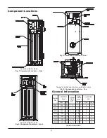
Страница 6: ...cations Top Fig 3 Component Locations Rear Panels omitted for clarity Fig 2 Component Locations Front Model No MBTUH Input Water Conn NPT Gas Conn NPT Vent Size in Max Min N P Flue Intake 503A 500 70...

Страница 7: ...To determine the water temperature being delivered turn on a hot water faucet and place a thermometer in the hot water stream and read the thermometer NOTE When this water heater is supplying general...

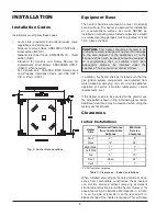
Страница 8: ...n in front 1 in on the side at least 24 in on the rear and 10 in above the top of the heater is required This will allow 8 Table C Clearances Indoor Installations INSTALLATION Installation Codes Insta...

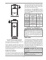
Страница 9: ...erhang unless clearances are in accordance with local instal Combustion and Ventilation Air Indoor Units This heater must be supplied with sufficient quantities of non contaminated air to support prop...

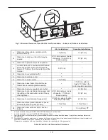
Страница 10: ...t 91 cm K Clearance to mechanical air supply inlet 3 ft 91 cm above if within 10 ft 3m horizontally 6 ft 1 83m L Clearance above paved sidewalk or paved driveway located on public property 7 ft 2 13m...

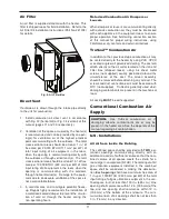
Страница 11: ...g connection section of this manual for proper wiring instructions using Fan Damper dry contacts and external interlock TruSeal Combustion Air In addition to the 3 previous steps combustion air may be...

Страница 12: ...l be provided by an opening s for ventilation air at the highest practical point communicating with the outdoors The total cross sectional area of such an opening s shall be at least 10 of the area re...

Страница 13: ...changer with water temperatures as low as 120 F 49 C Heaters operated with an inlet temperature of less than 120 F 49 C MUST have an approved low tem perature operation system Figs 10 and 11 to preven...

Страница 14: ...water source heat pump applications as well as some others An injector pump arrangement may be used to keep the heater loop at or above 120 F 49 C An injector pump approach has the added value of bei...

Страница 15: ...range of applications The installer design engineer should refer to the following Modes to determine which best fits the intended application and functionality for the unit being installed Type H mode...

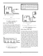
Страница 16: ...lower than the WWSD temperature setting if utilized unless an indirect call for heat is present with priority Fig 12 MODE 1 Single Boiler with Primary Secondary Piping Fig 14 MODE 2 Single Boiler with...

Страница 17: ...lieu of the Indirect DHW Sensor S5 See the Versa IC manu al for additional details Domestic Hot Water When designing the water piping system for domestic hot water applications water hardness should...

Страница 18: ...ains per gallon a water softener treatment system must be utilized Caution For scale free operation with Hard Water 16 25 grains per gallon of total hardness the operating control must NOT be set high...

Страница 19: ...s supply during any pressure testing of the gas supply system at test pressures in excess of 1 2 psi 3 45 kPa Gas Supply Pressure A minimum of 4 0 in WC upstream gas pressure under full load and a max...

Страница 20: ...to Terminals 1 2 and 3 as noted in Fig 18 All low voltage wiring including sensors interlocks enable disable and var ious options are wired into terminals 1 24 on the front wiring panel as noted in F...

Страница 21: ...Connected Controllers It is strongly recommended that all individually pow ered control modules and the heater should be supplied from the same power source NOTE Field supplied isolation relays should...

Страница 22: ...up to 150 feet 4 Mount the outdoor sensor on an exterior surface of the building preferably on the north side in an area that will not be affected by direct sunlight and that will be exposed to varyin...

Страница 23: ...tion 2 When the Indirect DHW call for heat is active the PIM communicates this to the VERSA The VERSA calculates the optimal operation and sends the firing rate and pump output requests to the PIM so...

Страница 24: ...nnections are dry contacts rated for pilot duty only 5A maxi mum 2 Connect the boiler pump enable wires to the termi nal block at the rear of their unit The connections are dry contacts rated for pilo...

Страница 25: ...pump outputs are not used in the Cascade Follower configuration Fig 27 VERSA Follower Modbus BMS Communication The VERSA IC control is equipped as standard with a communications port for connectivity...

Страница 26: ...ANSI Z21 Standard and the NFGC U S or B149 Canada or applicable provisions of local building codes WARNING Contact the manufacturer of the vent material if there is any question about the appliance ca...

Страница 27: ...exterior finishes Use a rust resistant sheet metal backing plate against brick or mason ry surfaces 12 DO NOT extend exposed vent pipe outside of building beyond the minimum distance required for the...

Страница 28: ...r door which can be opened in any building any non mechani cal air supply inlet to any building or the combustion air inlet of any other appliance 8 Underneath a verandah porch or deck unless the vera...

Страница 29: ...The horizontal portions of the vent shall also be supported for the design and weight of the material employed to maintain clearances and to prevent physi cal damage or separation of joints NOTE A ven...

Страница 30: ...NOT it MUST be replaced NOTE For extractor sizing typical CO2 levels are 9 0 for natural gas and 10 2 for propane gas and flue temperature of 300 F at 100 firing rate meas ured at test port 12 above...

Страница 31: ...tallation These installations utilize the heater mounted blower to vent the combustion products to the outdoors Combustion air is taken from inside the room and the vent is installed horizontally thro...

Страница 32: ...t vent cap must be used sales order option D 15 The vent terminal must be located NO CLOSER than 12 off the wall Table M Category IV Horizontal Vent Horizontal Direct Vent Direct Vent Vertical Install...

Страница 33: ...eaves debris etc The stainless steel flue direct vent cap must be fur nished by the heater manufacturer in accordance with its listing sales order option D 15 Outdoor Installation Outdoor models must...

Страница 34: ...e equipment before servicing NOTE Condensate can freeze on the vent cap Frozen condensate on the vent cap can result in a blocked flue condition Ignition Control Functions When there is a call for hea...

Страница 35: ...of the gas valve on the inlet flange to the gas valve and is accessible through the removable access panels on the side or front of the heater to reset the gas pressure switch as necessary It is used...

Страница 36: ...C Control I O Manual Catalog 5000 72 Adjusting the MVB Setpoint To adjust the setpoint on the MVB Use the MENU key to scroll to the SETUP ADJUST menu then use the ITEM key to scroll to the SET POINT i...

Страница 37: ...3 Current system supply temperature Boil OUTLET All Current boiler outlet temperature Boil INLET All Current boiler inlet temperature Boil T All Current temperature difference between boiler outlet an...

Страница 38: ...rature 220 F TARGET MIN H MODE 1 2 3 OFF 50 F to 190 F Minimum target system temperature 50 F TARGET DIFF H MODE 1 2 3 2 F to 42 F Differential for target system temperature 10 F DHW SENSOR H MODE 1 2...

Страница 39: ...fset OPERATOR All Operator Limit Potentiometer PIM setting AUTO DIFF H MODE 1 2 3 Current auto differential PUMP PREPt All Duration of pump prepurge BLOW PREPt All Duration of blower prepurge BLOW PRE...

Страница 40: ...oiler outlet temperature Press UP DOWN for 1 sec to clear INLET HI All Records the highest boiler inlet temperature Press UP DOWN for 1 sec to clear INLET LO All Records the lowest boiler outlet tempe...

Страница 41: ...degree the outdoor temperature drops the tempera ture of the heating water will increase one degree With the VERSA both ends of the slope are adjustable It is factory set at 70 F water temperature Bo...

Страница 42: ...ual temperature where the building is located This temperature is used when completing heat loss calculations for the building Boiler Design Boil DESIGN The Boil DESIGN temperature is the water temper...

Страница 43: ...43 WIRING DIAGRAM Models 503A 2003A...

Страница 44: ...Follow the gas supplier s instructions If you cannot reach your gas supplier call the fire department Use only your hand to turn the gas control valve handle Never use tools If the handle will not tur...

Страница 45: ...roximately 15 seconds after the blower starts the igniter should start to glow observable through the observation port located at the front below the gas valve Look into the sight glass located just b...

Страница 46: ...ion USER TEST is displayed in the Title Field UP keystrokes are used to advance through the user test The Boil MIN MAX steps for burner operation are only run for enabled boilers Local Heat DHW EMS de...

Страница 47: ...point B bleedle valve and open the upstream manual gas valve Make sure that test point A B bleedle valves have been opened so as to allow gas to flow This will bring gas pressure to the second valve s...

Страница 48: ...allow one time operation of the limit and then must be returned to normal operation by turning dip switch 8 back to the OFF position Power to the unit must then be cycled off then on to return to nor...

Страница 49: ...ater temperature or manual reset high limit is not tripped c Enable Disable circuit is closed d Gas is on at the meter and the heater e Incoming dynamic gas pressure to the gas valve is NOT less than...

Страница 50: ...replace control DELTA T Temperature difference between the inlet and outlet exceeded the set point Check water flow LOW 24VAC Low 24 VAC power Check power supply wiring and transformer BLOW SPEED Blow...

Страница 51: ...the gas supply See table for more information 4 flashes N A N A 5 flashes Low Voltage Fault Check the 24 VAC input voltage The voltage must be above 18 0 VAC 6 flashes N A N A 7 flashes Hi Limit Fault...

Страница 52: ...c tion deterioration or leakage 4 Visually inspect for proper operation of the con densate drain in the venting If leaks are observed repair at once 5 Check air vents for leakage Yearly Beginning Of E...

Страница 53: ...see light blue flame at full input rate Weekly For low pressure heaters test low water cut off device With heater in pre purge depress the low water cut off test button Appliance should shut off and i...

Страница 54: ...sure Vessel Code Section IV Filter Maintenance Inspect quarterly Replace when tracking pressure exceeds 0 5 in WC at 100 fan speed except for models 1003A 1753A and 2003A which need to be replaced whe...

Страница 55: ...ontaminated ar eas this may also experience deterioration Products causing contaminated combustion air spray cans containing chloro fluorocarbons permanent wave solutions chlorinated waxes cleaners ch...

Страница 56: ...wall horizontally vented gas fueled equipment installed in every dwelling building or structure used in whole or in part for residential purposes including those owned or operated by the Commonwealth...

Страница 57: ...PLACEMENT Under this Warranty Raypak will furnish a replacement for any failed part The failed part must first be returned to Raypak if requested with transportation charges prepaid and all applicable...

Страница 58: ...utes Vent Size _____________ Stack Height _______ Low Water Cutoff _______________Test Category _________ sketch vent on reverse side Number of Tanks and Size Qty____ _______Gallons Vent Material ____...

Страница 59: ...59...

Страница 60: ...60 www raypak com Raypak Inc 2151 Eastman Avenue Oxnard CA 93030 805 278 5300 Fax 805 278 5468 Litho in U S A...


Отзывы: