background image

78

RAYDATA Installation and Operation Handbook

N

Nav Chapter

54

NAV key

25

NMEA data

71

P

Packing list

7

Pilot Heading

59

Position

55

Problem solving

61–65

R

Repeater mode

31, 70

Reset

63

Response level

31

Rudder angle

58

S

Sea Temperature

48

SeaTalk data

71

Self Test

63

Servicing

64

Setting alarms

36–41

Setup

27–34

Options

28

Using

28

Shallow Alarm

46

Adjusting

37

SOG (Speed Over Ground)

52, 56

Sounder control

31

Speed

Calibration

31

Over Ground (SOG)

52, 56

Through water

50

Speed Chapter

50–53

SPEED key

25

T

Temperature

48

Temperature Alarm

48

Adjusting

40

Time & Date

55

Transducer types

8

Trend indicator

20

Trip

53

TTG/ETA/VMG

57

Turning the RayData on and off

18

U

Up key

25

V

VMG

57

W

Waypoint/Bearing/Distance

56

81090-2

Содержание Raydata

Страница 1: ...d to navigation Its accuracy can be affected by many factors including equipment failure or defects environmental conditions and improper handling or use It is the user s responsibility to exercise co...

Страница 2: ...rk Portsmouth Hampshire PO3 5TD England Telephone 44 0 2392 693611 Fax 44 0 2392 694624 EUROPE Copyright Raymarine 2001 To the best of our knowledge the technical and graphical information contained i...

Страница 3: ...61...

Страница 4: ...man overboard warning Chapter 4 Provides instructions for setting up the RayData defaults such as the numerical units used to suit your prefences It also explains how to calibrate your speed transduce...

Страница 5: ...and follow the instructions in those chapters to make your changes Chapter 4 also explains how to calibrate the speed so that you obtain an accurate reading for your vessel If you experience any diff...

Страница 6: ...Installation and Service Guidelines 6 IMPORTANT NOTE 6 Installation 6 Check Before Going to Sea 7 Servicing and Safety 7 2 3 Packing List 7 2 4 Installing the Depth and Speed Transducers 8 Transducer...

Страница 7: ...3 5 Changing the Information Displayed 20 3 6 Changing the Lighting 22 3 7 Using the Locked Heading Facility 23 3 8 Man Overboard MOB 24 Sending an MOB Warning 24 Cancelling an MOB Warning 25 3 9 Key...

Страница 8: ...41 Alarm Notification 41 Dealing with an Alarm 42 Chapter 6 The Display Pages 43 6 1 Introduction 43 6 2 The Depth Chapter 44 Main Depth 44 Minimum Depth 46 Shallow Alarm 46 Deep Alarm 47 Anchor Alar...

Страница 9: ...Changing the Locked Heading 60 Locked Heading Over ride 60 Chapter 7 Problem Solving 61 7 1 Introduction 61 7 2 Fault Finding 62 7 3 Absent Data 62 7 4 Self Test Mode 63 7 5 Factory Reset 63 7 6 Main...

Страница 10: ...three line display showing depth speed and temperature can be selected Other displays show two to four items of related data on the screen at one time Operation of the RayData revolves around a Chapte...

Страница 11: ...Log and trip counters to indicate distance travelled on the current trip and the total travelled to date Sea surface temperature allowing you to detect suitable fishing sites and determine whether th...

Страница 12: ...Time and date Cross track error XTE distance Time to go TTG estimated time of arrival ETA and velocity made good VMG to the next waypoint Boat heading and rudder angle Facilities If the primary posit...

Страница 13: ...nction is to display data received from its own transducers However if it is connected to other instruments via SeaTalk interfaces the following information is sent or repeated to these other instrume...

Страница 14: ...connecting your RayData to a larger system you should refer to the installation instructions for the other units and for connection to the SeaTalk bus Note Before attempting any installation you shou...

Страница 15: ...ng or cables carrying radio signals e g VHF radios cables and antennas In the case of SSB radios the distance should be increased to 7ft 2m More than 7ft 2m from the path of a radar beam A radar beam...

Страница 16: ...ot affect performance There are no user serviceable parts in any Raymarine product Some products generate high voltages and so never handle the cables connectors when power is being supplied to the eq...

Страница 17: ...ding on your choice one of the following transducer sets is included Plastic through hull depth and speed transducers suitable for use with Glass Reinforced Plastic GRP Steel and Aluminium hulls with...

Страница 18: ...ast 6in 150mm from the keel with sailing yachts siting should be forward of the keel Near the centreline of the vessel Clear of other through hull fittings or projections Have sufficient clearance ins...

Страница 19: ...able These cables are fitted with female lug connectors that plug directly into the back of the RayData see below Allow some slack in the cables so that the equipment can be serviced if necessary Run...

Страница 20: ...nd cable running Although the RayData is designed to meet the CFR46 waterproofing standard it is advisable to mount it whenever possible so that it is not exposed to the direct effects of salt spray o...

Страница 21: ...3 16in 5mm holes for the thumb studs 5 Deburr the machined holes and fix the RayData to the panel using the four thumb studs and four thumb screws Trunnion Mounting To mount the RayData using the opt...

Страница 22: ...on using the knobs 8 provided 2 7 RayData Connections D3056 1 N M E A I N SPEED TEMP D E P T H SeaTalk s s s s Red Screen Yellow Blue Screen Black Red Green Screen Screen Red Yellow Red Blue Brown Whi...

Страница 23: ...cable to length and connect the red wire to 12V and the screen to 0V Protect the circuit with a 5A fuse circuit breaker Larger System If you are using the RayData as part of a larger system you will...

Страница 24: ...2 Installation 15 N M E A I N SPEED TEMP D E P T H SeaTalk s s s s D3033 1 N M E A I N SPEED TEMP D E P T H SeaTalk s s s s N M E A I N SPEED TEMP D E P T H SeaTalk s s s s NMEA in SeaTalk in out and...

Страница 25: ...16 RAYDATA Installation and Operation Handbook...

Страница 26: ...display and the functions of the keys and explains how to perform some basic operations It covers the following topics Using the keys Turning the RayData on and off The display Changing the informatio...

Страница 27: ...screen or mode three beeps sound to indicate that no response is available 3 3Turning the RayData On and Off When you turn on the power to the RayData the keys light up and the LCD display shows the s...

Страница 28: ...ormation shown on a display page are described below with reference to the illustration on the previous page DataValue The single line displays such as the example depth display each show the data val...

Страница 29: ...dicated by a symbol in the lower left corner of the screen Which key s to press to perform an operation such as changing or resetting a value see Chapters 4 and 5 An alarm warning message see Chapter...

Страница 30: ...pter Further sub pages are available using other keys For example with the main depth display on the screen press the key The minimum depth that has been encountered is displayed as shown in the follo...

Страница 31: ...een lighting and contrast 1 Press and hold the DEPTH key for one second The lighting control page appears This is a temporary display and reverts to the previous page if you do not press a key for fiv...

Страница 32: ...heading simply press and together from any page except those that indicate that this key combination is used for a different purpose The Locked Heading page is displayed as shown below D3064 1 This p...

Страница 33: ...RayData screen will display the message MOB NOT AVAILABLE If an MOB Master on the SeaTalk system responds the audible alarm stops and an MOB page such as the following is displayed D3071 1 This shows...

Страница 34: ...TS is used to Access the Depth Chapter of display pages which include depth and temperature displays and alarm controls Control the lighting and contrast level for the screen and the lighting level fo...

Страница 35: ...26 RAYDATA Installation and Operation Handbook...
Страница 36: ...nexpected results for example if you change the distance units from nautical miles to kilometres after travelling 50nm the log recording the total distance travelled will then read 50km You should kee...

Страница 37: ...ection 4 3 2 When the required menu is displayed press and together to select the menu The menu title is highlighted 3 Use the or key to scroll down or up the menu options or to decrease or increase t...

Страница 38: ...DEG C DEG F DEG F Distance Units KM NM SM NM Position LAT LON LAT LON TD only with NMEA input Variation Variation value 0 plus W or minus E up to 30 in whole degrees True Magnetic Mode TRUE MAGNETIC M...

Страница 39: ...e between the transducer and the keel as a negative value Waterline Increase the depth offset value to set it to the distance between the waterline and the transducer as a positive value The Depth pag...

Страница 40: ...d Depth Mode must be set to indicate the way in which your system is set up as follows Leave the mode set to Master if the transducer is connected to the RayData directly or if you wish to repeat dept...

Страница 41: ...and the RayData averages the information to obtain the calibration factor that will be used to correct the speed data displayed Select an easily identifiable measured distance from the chart between...

Страница 42: ...he run number returns to 1 if any of the runs were incorrect you can use the DEPTH key to select the required run number and then repeat the run if required 8 Press NAV to exit The Exit Speed Setup pa...

Страница 43: ...ue of 1 00 no calibration factor 5 Use the key to increase or the key to decrease the value as required 6 Press and together to set the new value Alternatively press NAV to cancel all changes The last...

Страница 44: ...w yourself time to respond to the alarm allow a greater margin if you are in areas where the bottom can shelve steeply Deep depth alarm which is activated when the water exceeds the specified depth Th...

Страница 45: ...tting alarms are part of the Depth Chapter and are accessed as shown in the diagram below SEA TEMP SPEED DEPTH TEMP MAIN DEPTH DEPTH DEPTH SHALLOW ALARM ADJUST DEPTH DEEP ALARM ADJUST ANCHOR ALARM ADJ...

Страница 46: ...ss and hold and together for six seconds The value s is replaced by the text ALARM OFF D3072 1 To turn the alarm back on press and hold and together for six seconds again The current alarm limit value...

Страница 47: ...the current alarm threshold value or ALARM OFF if the alarm is turned off To toggle the alarm between on and off press and hold and together for six seconds 4 Press and together The Shallow Alarm Adju...

Страница 48: ...imit must also be greater than the shallow alarm limit To adjust the deep depth alarm value 1 Unless you are continuing after setting the shallow alarm follow steps 1 to 3 in the Shallow Alarm procedu...

Страница 49: ...m the range is 5 to 104 F 10 to 40 C with a resolution of 0 1 To adjust the anchor or temperature alarm values 1 Display the appropriate alarm page For the anchor alarm press from the Deep Alarm page...

Страница 50: ...Main Depth page 5 3 Handling Alarms The RayData will respond to the alarms set internally as well as any external Watch alarms received from other instruments via the SeaTalk connection Alarm Notifica...

Страница 51: ...s on the display and the SeaTalk alarm remains active until the data value returns within the safe limits set You may wish to adjust the alarm limits depending on the current temperature or depth cond...

Страница 52: ...s information available For each chapter the individual pages and their sub pages are described in detail excluding the the alarm setup pages which are described in Chapter 5 The pages in the Setup Ch...

Страница 53: ...t minimum Press DEPTH key to return to main page D3066 1 DEPTH This section describes the following pages Main Depth Minimum Depth Shallow Alarm Deep Alarm Anchor Alarm Sea Temperature Temperature Ala...

Страница 54: ...dge of the display indicates the direction and rate of change of the depth An upwards arrow means that the bottom is rising that is the depth is decreasing The length of the trend arrow indicates the...

Страница 55: ...ll be displayed as the new minimum depth ShallowAlarm To display this sub page press once from the Minimum Depth page or twice from the Main Depth page D3047 1 This page shows the current setting of t...

Страница 56: ...shallow alarm limit AnchorAlarm To display this sub page press once from the Deep Alarm page or from the Main Depth page D3048 1 This page shows the current settings for the upper and lower values th...

Страница 57: ...TemperatureAlarm To display this sub page press from the Temperature page This page shows the current settings for the upper and lower values that will set off a temperature alarm or if the alarm has...

Страница 58: ...the SPEED to key access the Speed Chapter and scroll through the pages until this one is displayed see Section 6 3 D3049 1 This display combines the current depth speed and sea temperature data on a s...

Страница 59: ...imum This section describes the pages in the following order Speed Through Water Maximum Speed Average Speed Speed Over Ground SOG Log Trip 3 Line Page speed depth and temperature Note that the Speed...

Страница 60: ...e greater the difference between the current value and that shown in the previous update of the display The STW indicator in the bottom left corner of the screen serves as a reminder that this page sh...

Страница 61: ...Through Water value To reset the average speed value press and together The current speed will be displayed as the new average speed Speed Over Ground SOG To display this sub page press once from the...

Страница 62: ...seconds While you hold the keys down the trip value flashes until the counter is reset to zero If you release the keys after less than three seconds while the trip value is still flashing the trip wil...

Страница 63: ...ds or you will turn the RayData off The Nav Chapter consists of four main pages and four sub pages as shown in the diagram below WAYPOINT BEARING DISTANCE HEADING LOCKED HEADING POSITION NAV NAV NAV T...

Страница 64: ...e Setup pages see Chapter 4 The source of the information is also shown in the bottom right corner as follows D dGPS G GPS L Loran If the primary position data is lost the RayData uses the speed and h...

Страница 65: ...ypoint Bearing Distance To display this page press NAV from the Position page D3059 1 This display shows the number bearing and distance of the next waypoint The bearing is in degrees Magnetic or degr...

Страница 66: ...isplay the TTG ETA VMG sub page TTG ETA VMG To display this sub page press once from the BRG DTW COG SOG page or twice from the Waypoint Bearing Distance page D3061 2 This page shows the following add...

Страница 67: ...he Setup pages see Chapter 4 The response of the heading value is also determined by the Setup selection Press NAV to display the Locked Heading page or to display the Boat Heading sub page Boat Headi...

Страница 68: ...steering bargraph which provides a graphical indication of the difference between the two headings If the RayData is being used as part of a larger system with an autopilot connected to the SeaTalk bu...

Страница 69: ...for setting alarm values Note You cannot change the locked heading from the RayData if it has been locked by an autopilot as indicated by PILOT HEADING at the top of the display Locked Heading Over ri...

Страница 70: ...vides information and suggestions to help you to resolve any problems you may experience when setting up and using your RayData and to deal with maintenance and servicing The chapter covers the follow...

Страница 71: ...nector No speed through water Paddlewheel fouled Clean paddlewheel information Use Speed Over Ground display if available in interim No depth information Depth transducer Check cabling and security of...

Страница 72: ...nd of the Depth Speed and Temperature transducers 3 A test pattern sequence While the test pattern is displayed the display and key lighting cycles repeatedly through all levels off low and high for t...

Страница 73: ...time and money as well as prevent unnecessary and premature failures Always keep the unit as clean as possible Use a soft clean cloth for cleaning Do not use abrasive cleansers chemical cleaners or so...

Страница 74: ...n National Distributor who will be able to provide expert assistance If a problem arises that cannot be resolved you should remove the RayData from its mounting unplug the cabling and return the unit...

Страница 75: ...66 RAYDATA Installation and Operation Handbook...
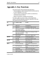
Страница 76: ...off after 3 seconds P System is on and navigational Nav Chapter main page last used displayed data available via SeaTalk or NMEA non Nav Chapter page P System is on and navigational Moves on to next m...

Страница 77: ...ailability indicated Next sub page displayed on display P Value adjustment indicated Increases right most digit of value by 1 on display H Alarm value and Locked Increases value quickly until key rele...

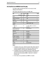
Страница 78: ...derived from the direct connected depth and speed transducers If you are using your RayData as part of a larger system the data displayed may be received from other sources via SeaTalk or NMEA connec...

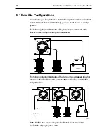
Страница 79: ...d transducers D3037 1 N M E A I N SPEED TEMP D E P T H Sea Talk s s s s Fuse 5A 12VDC The following diagram illustrates a RayData unit as a master together with two further RayData units as repeaters...

Страница 80: ...ed Over Ground Date Time ZDA RMC Waypoint ID RMB BWC XTE RMB APB APA Bearing To Waypoint RMB BWC Distance To Waypoint RMB BWC Rudder Angle No fix GGA Variation RMC RMA HDG Notes 1 A RayData unit set u...

Страница 81: ...72 RAYDATA Installation and Operation Handbook...

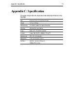
Страница 82: ...1 8 11 2 x 11 0 x 4 5 cm Weight 12 3 oz 0 35 Kg Waterproofing To CFR46 suitable for external mounting Mounting Panel with trunnion options Power External 10 16 volts DC required Controls 5 keys NAV D...

Страница 83: ...74 RAYDATA Installation and Operation Handbook...
Страница 84: ...displayed on the screen at one time Repeater An instrument that displays data it has received without modification SeaTalk The Raymarine standard for data communications Sub page A secondary page with...

Страница 85: ...rence in time of arrival measured in microseconds of the two Loran signals one from the master transmitting station and the other from the secondary TTG Time To Go VMG Velocity Made Good The component...

Страница 86: ...ces 69 Dead Reckoning 55 Deep Alarm 47 Adjusting 39 Depth Main 44 Minimum 46 DEPTH LIGHTS key 25 Depth Chapter 44 49 Depth offset 30 Disabling alarms 37 Display components 19 Display Pages 43 60 Dista...

Страница 87: ...Test 63 Servicing 64 Setting alarms 36 41 Setup 27 34 Options 28 Using 28 Shallow Alarm 46 Adjusting 37 SOG Speed Over Ground 52 56 Sounder control 31 Speed Calibration 31 Over Ground SOG 52 56 Throug...

Отзывы: