2-8 Installation
2.4.3 NMEA Data (Requires Full Function Handset)
When an optional Full Function Handset is installed enabling Class “D”
DSC functionality, inputting NMEA data will provide position information
to the radio. The RAY215E accepts NMEA 0183 data from a position
determining device (GPS, etc.) to provide the Latitude and Longitude
position information that is transmitted during a DSC Distress Call.
When the Full Function Handset is present but no valid NMEA signal is
detected, the NMEA indicator flashes continuously.
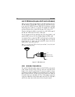
Connect the input(s) of the positioning device to the blue (NMEA+) and
purple (NMEA-) wires in the Power/Optional Speaker/NMEA cable.
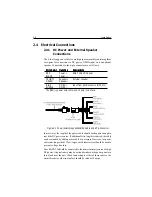
An example of how to connect the NMEA cables and power supply using
a suitable connector block is shown in the diagram below. For specific
instructions how to connect your particular GPS, please refer to the
handbook that came with that device.
Note:
For non-differential GPS, all return connections (-) must be tied to
a common ground reference.
+12 V
0V
+ NMEA Data (blue)
-- NMEA Data (purple)
Red
Black
Yellow
Figure 2-5 GPS Connections
2.4.4 Antenna Connections
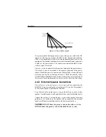
The coaxial VHF antenna cable connects to the RAY215E antenna cable
on the rear panel using a PL259 VHF type connector. The antenna cable
length can be critical to performance. If you are uncertain, contact a
professional installer or call Raymarine Product Support. If a longer cable
length is required, RG-58 (50 ohm) coaxial cable or equivalent cable can
be used for runs up to a maximum of 50 feet. If the distance required is
even greater, Raymarine recommends using low loss RG-213 or equivalent
cable for the entire run to avoid excessive losses in power output.
Содержание Ray215e
Страница 1: ...O w n e r s H a n d b o o k VHF Radio Ray215e...
Страница 2: ...RAY215E Modular VHF Radio Owner s Handbook Document number R49018_2 Date April 2002...
Страница 3: ......
Страница 23: ...2 10 Installation Figure 2 6 Typical Grounding Method...
Страница 115: ...4 60 Operation with Full Function Handset...
Страница 121: ...5 6 Maintenance This page intentionally left blank...
Страница 122: ...5 7 Maintenance 5 4 Drawings Assembly Drawing...
Страница 123: ...5 8 Maintenance Block Diagram RF PCB...
Страница 124: ...5 9 Maintenance Control PCB...
Страница 125: ...5 10 Maintenance Front PCB Microphone PCB...

