background image

Chapter 3: Getting Started

3-5

Op

er

at

in

g Contr

ols

3.3 Operating Controls

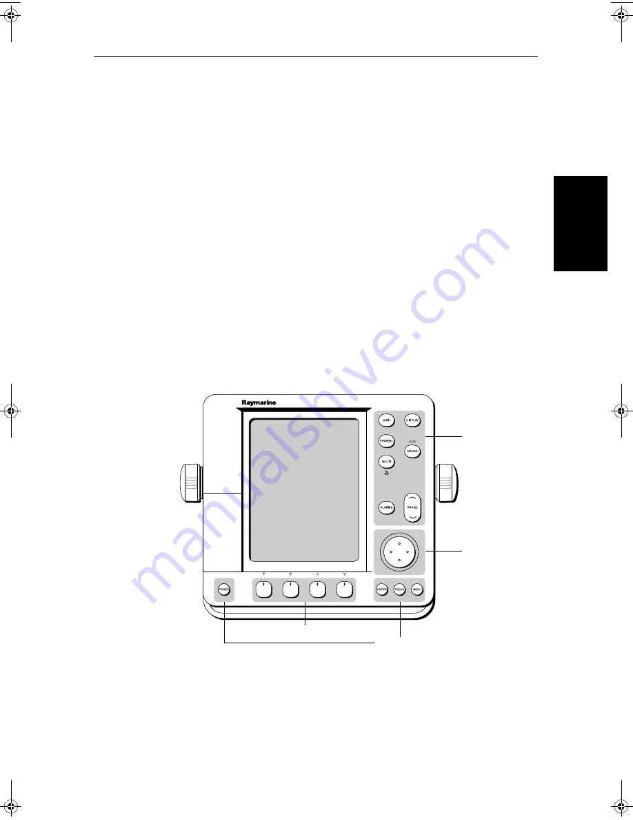
You operate the fishfinder and chart systems using a variety of controls:

A trackpad providing up, down, left, right and diagonal control of an on 
screen cursor

Eleven dedicated (labeled) control keys 

Four soft keys with labels displayed on the screen

Pop-up menus, displayed on-screen, from which you select options

Database lists, displayed on-screen, which enable you to edit items

Note: 

The cursor is the cross-hair symbol (+) visible on the display. You move 

the cursor using the trackpad and use it to select a position or item on the 
chart.

The control keys are shown in 

Figure 3-5

. They are back-lit for night-time use 

when the display brightness is dimmed. When you use a control, a help 
message is displayed at the top of the screen (unless you switch help off as 
described in 

Chapter 4

). The following paragraphs describe the controls and 

on-screen facilities.


Figure 3-4:

7" LCD Display Control Keys

Dedicated
keys

Trackpad

Soft keys

Dedicated keys

D3596-4

81213_1.book  Page 5  Monday, March 17, 2003  1:14 PM

Содержание L1250DRC

Страница 1: ...HD Series Fishfinders Owner s Handbook Document number 81213_1 Date February 2003...

Страница 2: ......

Страница 3: ...serviceable parts or adjustments The operator should never remove the unit cover or attempt to service the equipment CAUTION Removing the transducer cable from the fishfinder display or the DSM250 whi...

Страница 4: ...odule ThecombinedFishfinder Chartplotterdisplayunitsincludeacartridgeholder assembly that contains two slots for C MAP NT or NT chart cards Digital Sounder HD Series Fishfinders come packaged with a D...

Страница 5: ...erfectly normal effect that will be seen with all color LCD displays IncommonwithallThinFilmTransistor TFT LCDdisplays thescreenmay exhibit a few less than 20 wrongly illuminated pixels These may appe...

Страница 6: ...plete the owner information and return the card to the factory in order to receive full warranty benefits WARNING CUTTING THE TRANSDUCER CABLE WILL VOID THE WARRANTY OPENING A SEALED UNIT BY ANYONE OT...

Страница 7: ...ed trademark of Raymarine Limited hsb2 is a trademark of Raymarine Limited Pathfinder Plus is a trademark of Raymarine Limited ThisproductcontainstechnologyprovidedunderlicensebyAcornGroupplc The copy...

Страница 8: ...viii HD Series Fishfinders...

Страница 9: ...hfinder Display 1 8 Fishfinder Options 1 10 Fishfinder Functions 1 11 1 3 The Chartplotter Display 1 13 Chartplotter Display Options 1 14 Chartplotter Functions 1 16 Chapter 2 Installation 2 1 2 1 Int...

Страница 10: ...s 2 24 High Speed Bus hsb2 2 25 SeaTalk and NMEA In 2 27 2 10 Integrated System Checks 2 34 Chart Display 2 34 Received Data 2 34 Transmitted Data 2 34 Chapter 3 Getting Started 3 1 3 1 Introduction 3...

Страница 11: ...Variation Source 4 8 Bridge NMEA Heading 4 9 NMEA Out Set Up 4 10 Cursor Echo 4 11 Date and Time Settings 4 12 GPS SOG COG Filter 4 12 Compass Set Up 4 12 Language 4 12 Simulator 4 13 4 4 Sonar Set U...

Страница 12: ...Controlling the Display 5 4 Selecting the Mode of Operation 5 4 Switching Between Sounder and Other Modes 5 10 5 3 Display Unit Control Functions 5 11 Viewing Data Boxes 5 11 Changing the Scroll Speed...

Страница 13: ...ying the Chart Data 7 3 Displaying Chart Object and Source Information 7 4 7 3 Working with Waypoints 7 8 Introduction 7 8 Placing a Waypoint 7 9 Selecting a Waypoint 7 12 Waypoint Data Display 7 13 E...

Страница 14: ...cks 7 40 SmartRoute 7 42 7 8 Typical Chart Scenarios 7 43 Place and Goto a Waypoint 7 44 Make and Follow a Route 7 46 Review Your Passage Plan 7 48 Chapter 8 Advanced Chart Operations 8 1 8 1 Introduc...

Страница 15: ...Europe 9 11 Worldwide Support 9 11 Appendix A Specifications A 1 HD Series Fishfinder Displays A 1 DSM250 Digital Sounder Module A 4 Appendix B Using the Auxiliary Junction Box B 1 Raystar 112 105 Ape...

Страница 16: ...xvi HD Series Fishfinders...

Страница 17: ...rate which along with the digital adaptive high sample rate receiver ensures that the entire water column is presented in superb detail and optimal color allocation HDSeriesFishfindersfeaturedualfrequ...

Страница 18: ...inder display unit and sounder module You should refer to it when you are ready to install the system Details to connect the display to other equipment via hsb2 NMEA and SeaTalk are also provided Chap...

Страница 19: ...he Quick Reference Cards supplied with your system Terminology The following terminology is used to describe the various display unit configurations Master A unit capable of sourcing specific data suc...

Страница 20: ...ludes 7 or 10 4 LCD display Trackpad Eleven dedicated labeled control keys Four soft keys unlabeled whose functionality changes Two slots for the C MAP NT or NT chart cards Raychart models only Digita...

Страница 21: ...og if appropriate data is available View fishfinder and chart simultaneously Choice of chart orientation Head Up Course Up and North Up DSM250 Digital Sounder Module The DSM250 module is waterproof to...

Страница 22: ...der only unit connected only sonar mode is available You can also set Windows On to split the display into two half screen windows horizontal or vertical to show supplementary data Depending on the ot...

Страница 23: ...ok supplied with that unit Note MARPA functionality is available on the fishfinder display if you have an integrated system with a Pathfinder radar master display that includes MARPA as a primary func...

Страница 24: ...Plus Series LCD or CRT displays to provide an integrated system Earlier HSB non Plus Display units can be upgradedtoprovidehsb2 compatibility SeeConnectinghsb2PlusSeriesUnits on page 2 26 for details...

Страница 25: ...what is displayed and how it is displayed including language and units For example you can set the scroll speed of the bottom graph display and you can select the range to adjust the depth displayed...

Страница 26: ...sed on the current depth Bottom Lock changes the operating mode to reset the bottom providing a bottom up view The bottom is used as the reference with its image flat tened Bottomlockmodeisusedprimari...

Страница 27: ...ottom graph is displayed in both frequencies split horizontally Zoom Bottom Lock or A Scope can be displayed with the dual frequency graph All of these options are available when the fishfinder is dis...

Страница 28: ...GC Z H 0 80 6 8 27 2 27 2 200kHz 50kHz 200kHz 200kHz 50kHz SPLIT 0 80 ZOOM FREQUENCY BTM LOCK A SCOPE AUTO GC Z H 200kHz 10 20 30 80 80 0 ZOOM FREQUENCY BTM LOCK A SCOPE AUTO GC Z H SPLIT D6202 1 0 X...

Страница 29: ...ssel is shown as a circle The chartplotter screen includes a status bar that displays chart scale with either cursor position range and bearing or when the cursor is homed to the vessel by pressing FI...

Страница 30: ...topilotstatus and locked heading information Display options are provided in System Set Up and Chart Set Up as described in Chapter 4 Chart set up options enable you to customize the chart by selectin...

Страница 31: ...ght sectors marine features Note The factory default for the CUSTOM settings is ON Icons are displayed in detail depth shading limit is 10 m and depth contour display is 0 100 m A complete list of cha...

Страница 32: ...e Nearest Port Place Move Erase and Edit a Waypoint Goto Waypoint or Cursor Create Save Name Edit and Follow a Route Review Route and Waypoint Lists Display vessel s track Save and Name the Track for...

Страница 33: ...er Once the display is operating correctly you can connect it to other equipment as described in Section 2 9Integrated Systems on page 2 24 taking particular care to ensure the correct polarity of the...

Страница 34: ...performance butitisrecognizedthatitmaynotbepossibletomeetallofthese conditions in all situations To ensure the best possible conditions for EMC performance within the constraints imposed by any locat...

Страница 35: ...ession Ferrites The following illustration shows typical cable suppression ferrites used with Raymarine equipment Always use the ferrites supplied by Raymarine Figure 2 2 Typical Suppression Ferrites...

Страница 36: ...5031 L770D L770DRC L1260D L1260DRC Handbook Fishfinder Chart Handbook Transducers Quick Reference Card Fishfinder Quick Reference Card Chart 81213 81196 86066 86067 All All All L770DRC L1260DRC Mounti...

Страница 37: ...t 10 m 60 ft 20m hsb2 In Line Terminator hsb2 Splitter Cable NMEA OUT cable assy 4 ft 11 in 1 5m R55001 R55002 R55003 R55004 E55010 R58117 E55040 R55005 All All All All All All All All Transducer and...

Страница 38: ...nnectors avoiding tight bends in the cable Interference The selected location should be far enough away from devices that may cause interference such as motors generators and radio transmitter receive...

Страница 39: ...ARKS ALARMS RANGE ENTER CLEAR MENU POWER Weight 8 1 lbs 3 7 Kg Compass Safe Distance 39 in 1 m 10 51 in 267 mm 0 95 in 24 3 mm 6 89 in 175 mm 0 4 in 10 mm 7 3 in 185 mm 8 1 in 205 2 mm 8 8 in 223 6 mm...

Страница 40: ...260D and L1260DRC Plus D5066 3 11 5 in 292 mm 3 82 in 97 mm 6 38 in 162 mm cable clearance Compass Safe Distance 39 in 1 m 12 9 in 328 mm 9 7 in 246 mm 0 87 in 22 1 mm 7 88 in 200 mm 1 7 in 43 mm 11 2...

Страница 41: ...o the panel connectors avoiding tight bends in the cable Interference The selected location should be far enough away from devices that may cause interference such as motors generators and radio trans...

Страница 42: ...ter tight feed through should be used Securecablesinplaceusingtie wrapsorlacingtwine Coilanyextracable and tie it out of the way You need to run the following cables Power NMEA Input cable supplied wi...

Страница 43: ...ansducer cable supplied with the transducer This 30 ft 10 m cable has a connector plug with an outer nut that you must attach at one end for the sounder module or extension cable The transducer cable...

Страница 44: ...bulkhead ordeckhead Figure 2 6 LCD Display Mounting 1 Loosen the knobs and remove the mounting bracket from the display unit 2 Mark the locations of the mounting bracket screw holes on the mounting s...

Страница 45: ...studs into the holes provided at the rear of the display 7 Connect the DC power cable HSB cable transducer cable and any other accessory cables to the display Avoid tight bends in the cables 8 Place t...

Страница 46: ...n the screw Before drill ing the pilot hole hand drill the marked location with an oversized bit and countersink to approximately 3 8 diameter 5 Drive the supplied 8 screws into the pilot holes Screw...

Страница 47: ...onnectorisnotusedwiththeHDSeriesFishfinders The transducer is connected to the DSM250 sounder module Figure 2 8 HD Series Fishfinder Display Connector Panel Thefollowingsectionsdetail the displayunitc...

Страница 48: ...er Negative grounded with the negative battery terminal connected to the ships ground Floating with neither battery terminal connected to the ships ground CAUTION This system is not intended for use o...

Страница 49: ...ound as previously described in Ground Connection on page 2 20 Any unused wires should be insulated and taped back Power for External Equipment External equipment cannot be powered from the display s...

Страница 50: ...complete list and associated part numbers The HSB cable is attached to the three pin male connector marked HSB on the connector panel of the sounder module and display unit The connector pins are sho...

Страница 51: ...o 32 V The power connection to the unit should be made at either the output of the battery isolator switch or at a DC power distribution panel Raymarine recommends that power is fed directly to the DS...

Страница 52: ...hip s power and plugged into the POWER connector on the connector panel Note You should locate the DSM250 so that the power cord can be easily re moved if necessary If the sounder is placed in a diffi...

Страница 53: ...connector and Y shaped connector if supplied has a nut that has been removed to aid installation To enable you to complete the installation without cutting the cable ensure that any holes you drill ar...

Страница 54: ...a transducer extension ca ble ensure that you connect the Y cable to the sounder module and the exten sion cable to the transducer The connector pins are shown in the following diagram together with...

Страница 55: ...ucer cable is accidentally removed while the DSM250 is powered on remove power from the sounder module replace the transducer cable and then return power to the module As a safety feature the DSM250 o...

Страница 56: ...her equip ment Some incoming data can be converted across the communication link and re transmitted Power for External Equipment External equipment cannot be powered from the display s SeaTalk interfa...

Страница 57: ...d a remote hsb2 Series Plus Chartplotter to provide fishfinder chart and radar functionality on all three displays You can display some combinations such as fishfinder chart or radar chart in half scr...

Страница 58: ...e connected at a maximum of 40 meters cable length 2 Asoftware onlyupgradeenablesthedisplaytobeusedwithaPlus orPlus upgraded unit in the hsb2 system However liketheoldHSB non Plus system thisconfigura...

Страница 59: ...ly Like the old HSB system this configuration only supports two displays twosoftware onlyupgradedunitsoronesoftware onlyupgradedwithone true Plus or Plus upgraded display An In Out connector cable is...

Страница 60: ...ure data are available on SeaTalk the Fish finder uses thisdata if thisdataisnot on SeaTalk from otherinstruments it is transmitted by the Fishfinder For details of received data refer to the table in...

Страница 61: ...flexible enough to adapt to any number of instruments without a central processor SeaTalk equipment can also communicate with non SeaTalk equipment via the NMEA standard SeaTalk Connection SeaTalk dat...

Страница 62: ...splay and a SeaTalk instrument or the SeaTalk bus Standard SeaTalk cables are available in a range of lengths part numbers D284toD287 CablesforconnectingtoSeaTalkunitswithroundconnectors are also avai...

Страница 63: ...ta if not provided via SeaTalk Connect the input s to the orange and yellow wires Channel 1 and or the greenandbluewires Channel2 RefertoPowerandNMEAInputConnector on page 2 16 for further details For...

Страница 64: ...r to check the connections Figure 2 20 shows how to connect the junction box Appendix B provides connection details for specific Raymarine Apelco and Autohelm GPS and Beacon Receiver systems Figure 2...

Страница 65: ...edtootherinstruments For example if youhaveamaster andarepeaterdisplay you onlyneedtoconnect NMEA In to the master display which will pass the data to the repeater via SeaTalk You can prevent NMEA hea...

Страница 66: ...the center of the chart display 3 Insert a chart cartridge for the area of your vessel Use the RANGE key to zoom in to check that the chart data is being dis played Received Data If either SeaTalk or...

Страница 67: ...e power cord is attached to ship s power and plugged into the POWER connector on the connector panel Note The DSM250 should be located so that the power cord can be easily re moved if necessary If the...

Страница 68: ...notnormallyanissuebecausethedisplayunitissetastheREPEATER by default However ifyouhavechangedthissetting youmustreturnthedisplay to be a REPEATER To set the display unit to be the sonar repeater 1 Pre...

Страница 69: ...eves to be accurate However you should not rely on these displays as yourprimarysourceofnavigation Rather yourRaychartshouldbeused onlyasabackuptoofficialgovernmentchartsandtraditionalmethodsof naviga...

Страница 70: ...switch the display unit off press and hold the POWER key for three seconds A countdown timer is displayed as shown below Figure 3 3 Switch Off When the counter reaches zero a beep sounds and the displ...

Страница 71: ...splayed on screen which enable you to edit items Note Thecursoristhecross hairsymbol visibleonthedisplay Youmove the cursor using the trackpad and use it to select a position or item on the chart Thec...

Страница 72: ...a position on the screen Select an item for example chart object on the chartplotter Pan the chart display Moving the Cursor You can press on any of the four sections of the trackpad to move the curs...

Страница 73: ...a text label appears to identify the feature as follows Some items on the fishfinder chartplotter screen such as the cursor have information associated with them Most information is displayed in a da...

Страница 74: ...ge chart scale RANGE for example ii A pop up menu is displayed providing further options iii A set of soft keys is displayed providing further functions As you press a key a single audio beep confirms...

Страница 75: ...onthescreenjustabovethekeys Thedefaultsoftkeysaredisplayed until you press a key or select an item on the screen the soft keys associated with the action are then displayed Thecurrently selectedsoftke...

Страница 76: ...to indicate that no response is available If desired you can turn the key beeps off as part of your set up procedure see Chapter 4 Pop Up Menus Pop up menus usually provide set up options When a pop u...

Страница 77: ...rt models only modes without data from the transducer or GPS system If you have not yet installed the full fishfinder system you can still operate in Simulator mode by connecting the module and displa...

Страница 78: ...up is displayed 3 Use the trackpad to move the selection bar over the option SONAR SIMULATOR The simulator soft keys are displayed 4 Press the ON soft key to switch on the sonar simulator 5 Press ENT...

Страница 79: ...aspects such as the screen and help setting Note All settings described in this chapter are retained when the unit is pow ered off However there is a one minute delay from the time you make the set ti...

Страница 80: ...s and their possible settings and describe the function of each parameter in turn To change the default settings 1 Press the MENU key to display the set up soft keys The options available depend on th...

Страница 81: ...yed This setting is retained when you move the selection bar on to the next parameter in the menu list For sliders press the appropriate soft key repeatedly to increase or decrease the slider value in...

Страница 82: ...DING LOG TRIP PILOT VMG TEMPERATURE TIDE SET DRIFT OFF LAT LONG or TDs OFF or ON OFF or ON OFF or ON OFF or ON OFF or ON OFF or ON OFF APPARENT TRUE BOTH OFF LAT LON RNG BRG TTG OFF or ON OFF or ON OF...

Страница 83: ...N OFF or ON OFF or ON OFF or ON OFF or ON OFF or ON OFF or ON OFF or ON OFF or ON OFF or ON OFF or ON OFF or ON OFF or ON ON ON ON ON ON ON ON ON ON ON ON ON ON ON ON ON ON ON ON CURSOR ECHO RADAR CUR...

Страница 84: ...as a group during normal operation You can also move them around the screen individually using the context sensitive cursor Refer to Viewing Data Boxes on page 5 11 Bearing Mode Note This option only...

Страница 85: ...ox es on and off during normal operation viatheSCREENdefaultsoftkey seeSwitchingtheCursorDataBox On and Off on page 5 23 Day Night This option enables you to change the display between day and night m...

Страница 86: ...key Ifyousetavaluehere themenusandsoftkeylabelswillbeclearedifakeyhas not been pressed for the specified number of seconds This setting does not affect the defaultsoft keylabels which are controlled...

Страница 87: ...available Manual Mode If you select Manual mode by pressing either of the MANUAL keys you can specify the local variation value according to the area in which you are operating Press the appropriate M...

Страница 88: ...erodepthsentbythefishfinder and the actual depth sent by the ST60 Turning OFF the DPT sentence disables the reading from the fishfinder The factory default for all NMEA sentences is transmission ON Di...

Страница 89: ...owsits own cursor plus the cursor of the other display with appropriate cursor text RDRorCHRT toindicateitsorigin Thismeansthatyoucouldmovethecursor overatargetontheradardisplayandchecktheidentityofth...

Страница 90: ...de to side as well as in the direction of the vessel Slow moving vessels or vessels sailing in rough seas will benefit from a high setting whereasapowerboatthatcanquicklychangespeedanddirectionwill be...

Страница 91: ...peration showing the simulation selected Fishfinder simulator mode is set in the Sonar setup menu as described in Section 4 4 4 4 Sonar Set Up Parameters The SONAR SET UP option enables you to set up...

Страница 92: ...transducer is connected This setting was originally established for networks that have multiple hsb2 Series Fishfinders for designating whether the Fishfinder is a MASTER directly displaying sonar dat...

Страница 93: ...ter The temperature calibrate option enables you to adjust the displayed temperature You can adjust the displayed temperature by 9 0 F to 9 0 F Sonar History Sonar History determines the number of dat...

Страница 94: ...s features and functions All controls are functional in Simulator mode with the exception of STC Version Serial Numbers TheareaatthebottomoftheSonarSetupscreengivesversioninformationfor the system Th...

Страница 95: ...the chart features are displayed Most options can be toggled between on off and custom Custom passes on off control to the SCREEN soft keys see Customizing the Screen Presentation Options on page 5 23...

Страница 96: ...SCREEN soft key in chart mode Plotter Mode PlotterModeenablesyoutozoomintoasmallerarea evenwhennochartdata is available for that scale This enables you use the chartplotter functions at large scales e...

Страница 97: ...DE or SUNLIGHT the display uses The Sunlight palette is optimized for best display clarity in bright sunlight In dimmer conditions you may prefer the shade palette Waypoint Options Waypoint Symbols co...

Страница 98: ...ed GPS to the new mode using SeaTalk and NMEA set up commands A message shows whether the set up was successful or not WARNING Changing the chart datum does not cause any waypoint or routes stored in...

Страница 99: ...SET option then press the SET UP OFFSET soft key If necessary position offset is automatically toggled on 2 Use the trackpad to move the cursor to the desired vessel position the cur sor position is d...

Страница 100: ...4 22 HD Series Fishfinders Position Offset...

Страница 101: ...ishfinder or Chartplotter Raychart models only without data from the transducer or GPS system See for Section 3 4 for information on using simulator mode Changing the Brightness Color Settings The MUL...

Страница 102: ...00 Selecting the Background Color Five colors are available for the fishfinder display background black dark gray light gray white and dark blue The color you select is used on all the fishfinder wind...

Страница 103: ...HRESH soft key The color threshold soft keys are dis played below color indicator showing the available echo colors Theweakest color is at the bottom of the indicator with the strongest color at the t...

Страница 104: ...describes how to select the mode of operation and switch half screen windows on off The following sections describe how tosetupthedisplayfortheFishfinderandfortheChart forfishfinderdisplays with chart...

Страница 105: ...lecting the Mode Using the DISPLAY Key Horizontal Half Screen Window Options Using horizontal half screens the main operating mode is displayed in the upper window you choose what is displayed in the...

Страница 106: ...t mode press the DISPLAY key Thefollowingsoft keysare displayed withanimageofeach availablewin dow Fishfinder Chart 2 In Sonar mode set SPLIT to HOR To select a different window press either SELECT WI...

Страница 107: ...225 T 40 30 20 20 10 10 nm nm WPT BRG WPT RNG TTG 1 45nm 23 1nm 01h 13m STEER STARBOARD WAYPOINT 001 351 T SELECT WINDOWS WINDOWS OFF ON SPLIT HOR VER 0 20 40 20 40 ft ft 60 60 60 60 CDI Window BDI Wi...

Страница 108: ...available each window provides several large format data boxes for specific information as follows Data Window A provides surface temperature with a 30 minutetempera ture graph speed through water an...

Страница 109: ...INDOW OPTION CHART SONAR LOG RADAR ZOOM FREQUENCY BTM LOCK A SCOPE AUTO GC F 50kHz 0 DEPTH ft SPEED kts 20 1 15 1 10 1 F 30 0 MINUTES 20 40 TEMPERATURE D6207 1 SELECT WINDOWS WINDOWS OFF ON SPLIT HOR...

Страница 110: ...sounder and chart display The current active display is highlighted in red on the CHRT SNR label and the cursor appears in that window Alternatively when you have both sounder and radar displayed in...

Страница 111: ...hich data is displayed in the boxes during system set up as described in Chapter 4 The default databoxpositionsarealongthebottom of thedisplay Eachboxcan bemoved to the desired position on the screen...

Страница 112: ...n 0 5 15 kts scroll speed varies linearly with boat speed Greater than 15 kts scroll speed is constant at 100 Youcan alsopause the display in either manual or automatic mode The depth indication conti...

Страница 113: ...s you can select either LO or HI power LO power 100 W is normally used in depthrangesless than8 ft 2 4m and HI power 600 or 1000 W dependingon your transducer is typically selected for depths greater...

Страница 114: ...n arrow to select a deeper range Table 5 2 Range and Shift Values Feet Fathoms Meters Range Shift Range Shift Range Shift 5 1 1 1 2 1 10 2 2 1 4 1 15 5 3 1 6 2 20 5 4 1 8 2 30 10 5 1 10 2 40 10 8 2 15...

Страница 115: ...selected see Selecting the Frequency on page 5 16 when the sounder completes the auto range hunt process the processisrepeatedintheotherfrequency IfMANUAL FREQUENCY isselected hunt mode only continue...

Страница 116: ...setting is also useful for automatically searching for bottom as described in Hunt Mode on page 5 15 Alternatively you can manually select either frequency or both frequencies simultaneously split fre...

Страница 117: ...hown as a straight line Note that some bottom features may extend above this line The actual depth reading is given in the bottom left hand corner of the Bottom Lock display RangeintervalsonBottomLock...

Страница 118: ...arrow to select a smaller range 5 Press ENTER or CLEAR to return to the default display Figure 5 7 Bottom Lock Display with Split Windows To reposition the bottom lock image 1 Usethetrackpad to movet...

Страница 119: ...PE MODE soft key to select one of the three modes for A Scope as demonstrated in Figure 5 8 i Mode 1 in which the A Scope image is angled outward as the signal width indicated with dotted lines increa...

Страница 120: ...If you select split windows the display is split vertically with the zoom image intheleft hand window and the scrolling bottom display in the right hand window See Figure 5 9 In a split window display...

Страница 121: ...turn off Zoom 1 Press the ZOOM soft key The Zoom soft keys are displayed 2 Press the ZOOM ON OFF soft key to toggle zoom off 3 Press ENTER or CLEAR to return to the default display If manual zoom is...

Страница 122: ...r you have moved the Zoom Position Line to the desired position press ENTER to reposition the zoom image or CLEAR to cancel the opera tion Figure 5 10 Repositioning the Zoom Window Selecting Zoom auto...

Страница 123: ...fromOFFtoONorfromON to OFF 3 To return to the default soft key display press ENTER You can move the cursor data box using the context sensitive cursor Switching Chart Grid On and Off The Chartplotter...

Страница 124: ...splay press ENTER If you turn the data boxes on and none are displayed you need to select the ones you require using the system set up menu as described in Section 4 3 To move any data box 1 Usethetra...

Страница 125: ...ethechartscaletozoomoutandintoanew areacenteredonthecur sor position This method is useful if the area you wish to see is a long dis tance away Changing the Chart Center You can move the area of the c...

Страница 126: ...hevesselatthecenter and the cursor homed onto the vessel When you press FIND SHIP the following occur The chart is re drawn with the vessel s position in the center The cursor is homed onto the vessel...

Страница 127: ...o move the display to another area of the chart by zooming out to a small scale chart then zooming in on another position centered on the cursor Each time you press the RANGE key the chart scale chang...

Страница 128: ...the RANGE key the effect depends on whether Plotter Mode is on or off as follows If Plotter Mode is Off the chart scale remains unchanged indicating the smallest chart scale is displayed IfPlotterMod...

Страница 129: ...page 5 26 to home the cursor onto the vessel When Radar Chart overlay is switched on the status bar indicates OVL If the option is switched on but the overlay is not visible because one of the above...

Страница 130: ...5 30 HD Series Fishfinders Moving Around the Chart...

Страница 131: ...Setting up and Using Alarms for fish shallow water and deep water Using a VRM to Determine Depth and Distance from Boat to a particular spot Placing Waypoints Using the Man Overboard MOB function Not...

Страница 132: ...ish it displays an arch shaped mark In general alarger archindicatesalargerfish thoughthisruleisnot alwaystrue Let ssaythat thereare twofishofthesame size oneisclosetothesurface the other isnear thebo...

Страница 133: ...a fish may be indicated by vertical lines In Bottom lock mode the fish arches may appear distorted as the bottom topography is removed from the image Bottom Indications The bottom usually produces a s...

Страница 134: ...e that the lower layer of the bottom is shown as a lighter gray this indicates a weaker echo This could mean that the upper layer is soft some sound waves may get through this layer and be reflected b...

Страница 135: ...ymarine recommends select ing AUTO mode for all Gain options If you change the settings the new GAIN COLOR GAIN or STC values and mode auto or manual remain set even when you turn off the display You...

Страница 136: ...ow and or murky water The automatic gain modes finds the ideal sensitivity level for you based on depth and water conditions Automatic gain modes take advantage the hardware s advanced DSP technology...

Страница 137: ...olors displayed You can use COLOR THRESHOLD with COLOR GAIN to determine how echoes are displayed The Fishfinder provides automatic or manual COLOR GAIN adjustment Automatic adjustment displays colors...

Страница 138: ...ealarm is displayed Youcannotset the shallow alarm to be deeper than the deep alarm Deep water You set depth at which the deep water alarm triggers When the depth is more than that set the buzzer soun...

Страница 139: ...LEAR to save the changes and clear the list To silence an alarm and clear the alarm message press any key 6 4 Using VRM to Determine Depth Distance from Boat The VRM variable range marker key is used...

Страница 140: ...RM on or re position an off screen VRM 1 Press VRM EBL The VRM is displayed in its last used position Thecursorispositionedatthecenterofthecrosshairand has controlof the VRM asindicatedbyfour wayarrow...

Страница 141: ...an event mark All waypoints placed on the Fishfinder are stored in a waypoint database list with position depth and temperature when it was placed WaypointsplacedontheFishfinderaredisplayedasasolidve...

Страница 142: ...yed 2 Press the MAKE NEW WAYPOINT soft key followed by LAT LONG TheWPT POSITION LAT LONG screen is displayed with itsassociatedsoft keys The waypoint is placed at the current vessel position or if not...

Страница 143: ...d reckoning To initiate the MOB procedure press and hold the MARKS key for two seconds The system then performs the following tasks automatically Marks the Fishfinder image with a vertical line and th...

Страница 144: ...o cancel the MOB press and hold the MARKS key for 2 seconds The MOB symbol and data box are removed Note The MOB procedure can also be initiated or cancelled if the appropri ate SeaTalk message is rec...

Страница 145: ...up and saving tracks All these chart functions are available in plotter mode so you can plot and track routes at large scales even when a chart card is not installed Further functions including measur...

Страница 146: ...ts can be downloaded The chart scale in use is indicated in the status bar the number represents the distance in nautical miles displayed from the top of the screen to the bottom of the screen Note Yo...

Страница 147: ...cks shut to prevent water from entering the card reader assembly Displaying the Chart Data Thenewchartinformationwillbedisplayedwhenyoumovethecursorintoan area covered by the new chart or if it is alr...

Страница 148: ...yed Three options are available Display a pop up for all objects and source data automatically when the cursor is over the object symbol or source area Display a pop up for displayed objects when the...

Страница 149: ...desthenameofthemarinaorportandalistof the facilities available Where available details for each facility can be displayed This information includes items such as accommodation slip sizes fueling sanit...

Страница 150: ...storms can alter tidal patterns and influence predicted times and heights The cursor represented by a dotted vertical line on the graph is used to select a time for which the tide height is displayed...

Страница 151: ...m at the center Goto a waypoint and display a list of all the port on the chart card To obtain the information for the nearest objects 1 Move the cursor to the desired position and then press ENTER to...

Страница 152: ...t mark A waypoint at the vessel position includes additional information if available on the depth and temperature when it was placed Alternatively you can manually enter Waypoints as either Lat Long...

Страница 153: ...on or at the vessel position 1 Press either the PLACE WPT AT CURSOR or the PLACE WPT AT VESSEL soft key The waypoint is added to the waypoint list and tagged using the next available number Thewaypoin...

Страница 154: ...ay press ENTER or CLEAR twice To place a waypoint as Loran TDs using the Waypoint List 1 Press MARK followed by the WAYPOINT LIST soft key The Waypoint List and associated soft keys are displayed 2 Pr...

Страница 155: ...ers as desired using i The CHAIN soft key which enables selection of both the Chain and it s Slave ii The ASF1 ASF2 soft key which presents two soft keys for editing ASF 1 and ASF 2 parameters indepen...

Страница 156: ...nd transfer waypoints To select a waypoint using the cursor 1 Move the cursor over the waypoint until the letters WPT are displayed TheWaypointDatabox seeWaypointDataDisplayonpage 7 13 andthe followin...

Страница 157: ...the waypoint data box and soft keys either Move the cursor away from the waypoint or press CLEAR To display the waypoint details from the waypoint list Select the waypoint in the list as described ab...

Страница 158: ...aracter as described in Using the ST60 or ST80 Navigator Keypad on page 7 16 When you have finished editing the name to remove the window press ENTER to save the name or CLEAR to cancel the operation...

Страница 159: ...t untilthelettersWPTaredisplayed The waypoint soft keys are displayed 2 Press the ERASE WAYPOINT soft key The waypoint is removed from the screen and the Waypoint List is updated Note If you have stop...

Страница 160: ...r ST80 Navigator Keypad If you have an ST60 or ST80 Navigator Keypad connected on SeaTalk it can be used to name or edit your waypoints tracks or routes on any display in the system Thekeypadcanalsobe...

Страница 161: ...character the selection bar moves to the first one in the list Each time the same key is pressed the selection bar moves to the entry starting with the next character on the key If no entry exists for...

Страница 162: ...e using the alphanumeric keys Use the del key to insert a space if required 3 Use the arrow keys and alphanumeric keys to input the remainder of the characters required to complete the editing 4 When...

Страница 163: ...urrent route to be overwritten by a route from an other unit on an integrated system so it is advisable to save all routes This section explains how to perform the following tasks Creating a new route...

Страница 164: ...aypoint list with the first avail able waypoint number The waypoints in the current route are re num bered to identify the new positions Note If you Clear the route before it is Saved the waypoint is...

Страница 165: ...e indicates the selected column and the trackpad up down to scroll through the lists 4 Select a waypoint from the Waypoint List then go to the New Route col umn and select a position in the list Note...

Страница 166: ...oute as described in Saving the Current Route Saving the Current Route Youcansaveupto20namedroutesintheroutedatabaselist Theseroutescan then be re displayed and followed at a later date When you save...

Страница 167: ...ht or left to the character you wish to edit Then use the top or bottom of the trackpad to increase or decrease the letter or number or Use the arrow keys and alphanumeric keys on the ST80 Navigator k...

Страница 168: ...e database press NO To save the route in the database press YES The Name route soft keys are displayed and you should continue as described in the previous section Saving the Current Route on page 7 2...

Страница 169: ...naboutarouteleg movethecursorovertheleguntilthe letters RTE are displayed A Route Leg data box such as the following is displayed To removethedatabox move the cursor away from the route or press CLEAR...

Страница 170: ...any route in the database 1 Press the ROUTE soft key followed by MORE then press ROUTE LIST The route list is displayed The selection bar indicates the selected route 2 Use the trackpad to select the...

Страница 171: ...ROUTE soft key followed by MORE then press ROUTE LIST The route list is displayed The selection bar indicates the selected route Press the appropriate soft key ERASE ROUTE or NAME ROUTE 2 If you ERAS...

Страница 172: ...The current routeisalwaysheldinposition 0inthedatabase soyouneedtoSavetheroute if you want to keep the changes Inserting a Waypoint into a Route Youcanusethecontext sensitivecursortoinsertoneormorewa...

Страница 173: ...a Waypoint from the Route To remove a waypoint from the current route 1 Move the cursor over the desired waypoint until the letters WPTare dis played The waypoint soft keys are displayed 2 Press the...

Страница 174: ...ypoints and restarting XTE Go to an individual point either an existing waypoint or the cursor Stop and Restart Follow Goto An alarm is triggered when you approach a waypoint this section describes wh...

Страница 175: ...e screen Press ENTER or CLEAR 3 Press the GOTO default soft key The Goto Follow soft keys are displayed 4 Press the FOLLOW ROUTE soft key The soft keys change as follows These options are described in...

Страница 176: ...opilotwillnot turn to the new waypoint until it is accepted at the autopilot control unit Other Follow Route Options You can use the soft keys to follow a route from a selected waypoint join a route o...

Страница 177: ...ack and want to go straight to your target rather than get back onto the original track To restart XTE 1 Press the GOTO default soft key the Follow Goto soft keys are displayed 2 PresstheRESTARTXTEsof...

Страница 178: ...places a temporary waypoint as the target and starts to navigate towards it The waypoint is shown as a square with a circle and dot in the center and is connected to the vessel s starting position wit...

Страница 179: ...rtplotter howeveryoucansave theroutelocally thusadding the waypoints to the local waypoint list Managing Database Lists There are several methods of maintaining database lists The method you choose wi...

Страница 180: ...and route lists 1 Insert a C MAP User Card into the lower of the two cartridge slots 1 Press MARKS followed by the LOAD SAVE USER CARD soft key 2 The User Card Menu and associated soft keys are displa...

Страница 181: ...the waypoint list on the chartplotter Routes transmitted on NMEA are appended to the route list 4 To disable waypoint transfer press the soft key STOP RECEIVING WAY POINTS Alternatively press ENTER o...

Страница 182: ...other will receive them WARNING Receiving waypoints from another hsb2 instrument overwrites any existing waypoint and route lists 1 Display the waypoint list as previously described then press the WA...

Страница 183: ...en if you want to display a saved track Breaks in the track will be caused when any of the following occur for longer than the specified track interval the track is switched off then on the position f...

Страница 184: ...can clear the current track from the screen When you select CLEAR TRACK if thecurrent track hasnot been saved you have the option of savingit To clear the current track 1 Press the CLEAR TRACK soft ke...

Страница 185: ...route press the YES soft key Use the trackpad to move the cursor right or left to the character you wish to edit Then use the top or bottom of the trackpad to increase or decrease the letter or number...

Страница 186: ...AR to return to the default display SmartRoute SmartRoute enables the current track or the last segment of a track with breaks tobeconvertedtoaroute thetrackcouldhavebeenretrievedfrom the tracklist Sm...

Страница 187: ...nctions Eachscenarioindicatesthekeypressesrequiredtoperformparticular tasks A typical chartplotter screen image is shown for each task The scenarios assume you have read the previous sections of this...

Страница 188: ...ries Fishfinders Place and Goto a Waypoint Place and Goto a Waypoint 1 Press MARKS 2 Position Cursor as required Press the soft key 1 2 3 Press the soft key to go to the waypoint selected by the curso...

Страница 189: ...pter 7 Standard Chart Operations 7 45 Place and Goto a Waypoint 4 The vessel navigates towards the target waypoint See Sections 7 3 Working wth Waypoints 7 5 Following Routes and Going to Points D4267...

Страница 190: ...ROUTE FIND SHIP MAKE ROUTE EDIT ROUTE CLEAR ROUTE MORE 2 2 Press the soft key 1 3 4 Press the soft key D4268 1 Press the soft key 1 Position Cursor in this example over an existing waypoint Position...

Страница 191: ...T XTE WAYPOINT ADVANCE STOP FOLLOW GOTO SCREEN ROUTE FIND SHIP 7 5 6 8 Press the soft key D4268 2d Press the soft key Press the soft key The route becomes the current route The vessel starts to naviga...

Страница 192: ...MAKE ROUTE EDIT ROUTE CLEAR ROUTE MORE 2 3 2 Press the soft key 1 4 5 Press the soft key Press the soft key D4269 1 Press the soft key 1 Use the trackpad to move selection bar over required route Time...

Страница 193: ...Passage Plan 6 Change the TIME to HOURS The display indicates it will take 32 minutes to reach the destination You can change the PLANNED SOG The display updates to indicate TIME required at the plann...

Страница 194: ...7 50 HD Series Fishfinders Review Your Passage Plan...

Страница 195: ...rboard MOB Cursor Echo Radar Overlay GPS Setup Data Log Mode Inordertousesomeofthesefunctions youmayneedthefollowingadditional data from equipment connected to your system via a SeaTalk hsb2 or NMEA l...

Страница 196: ...Ruler data box is displayed showing the bearing and distance from the starting point to the cursor position The character A appears at the cursor location 3 Use the trackpad to move the cursor to the...

Страница 197: ...to the previous position To clear the ruler line and ruler data box either Move the cursor over the ruler line until the letters A B are displayed then press CLEAR or Press VRM EBL the ruler soft keys...

Страница 198: ...ore obstruction You specify the depth and range of the sector from your vessel You can view a report of the objects that triggered the alarm Countdown The countdown timer has reached zero Alarm Clock...

Страница 199: ...rack and anchor alarm distances can be set in the range 0 01 to 9 99 nm in steps of 0 01nm Thegroundingalarmdepthcanbesetfrom1to20min1mstepsandcanbe specified to cover a sector at a range from 0 to 1n...

Страница 200: ...hechartat1 2nm evenifcartographyisnotavailablebutplotter mode is on Marks the current position with a MOB symbol which replaces any current active waypoint and route Displays the MOB data box which sh...

Страница 201: ...radar display or radar window default OFF Note The remote display must have SeaTalk Cursor Out enabled SeaTalk Cursor Out enables the output onto SeaTalk of the display s own cursor default OFF Cursor...

Страница 202: ...atus bar indication changes to OVL When Radar Chart overlay is switched on the soft key MORE provides access to the SCREEN soft key and to the radar controls TARGETS and MARPA The radar GAIN control i...

Страница 203: ...Figure 8 4 Navigation Status Window To tune a differential SeaTalk GPS to another beacon 1 Press D GPS SETUP the Differential GPS Setup pop up is displayed with MODE and BEACON SELECT soft keys 2 Pres...

Страница 204: ...entry Course Made Good CMG since last log entry Distance Made Good DMG since last log entry Once you have enabled the data log data is continually logged but you must set the display to Data Log Mode...

Страница 205: ...Press DISPLAY to select the chart mode then press ENTER The log continues until you return to the data log mode and press STOP LOG TIME POSITION CMG DMG CLEAR LOG STOP LOG 15 30 16 00 16 30 17 00 17...

Страница 206: ...8 12 HD Series Fishfinders Data Log Mode...

Страница 207: ...ld not remove the rear cover of the units WARNING REMOVAL OF A UNIT S COVER BY ANYONE OTHER THAN QUALIFIED SERVICE TECHNICIANS WILL VOID THE WARRANTY Switchoffthedisplayunitbeforeremovingthepowercord...

Страница 208: ...few weeks To prevent the build up of sea growth coat the transducer with a thin layer of paint Use only a water based antifoulingpaint orawater basedpaintspecificallydesignedfortransducers Apply the p...

Страница 209: ...e adjacent pieces of electrical equipment to interact withoneanother withaconsequentadverseeffectonoperation Inorderto minimisetheseeffectsandenableyoutogetthebest possibleperformance from your Raymar...

Страница 210: ...the following table which are reset to the factory default each time Factory Reset This resets all values back to their original factory settings WARNING The factory reset clears the Marks database a...

Страница 211: ...TS soft key appears 5 Press RESET TO DEFAULTS New soft keys appear ARE YOU SURE YES NO Pressing NO returns you to the Sonar Setup Menu Pressing YES causes the DSM250 to reset all settings to factory d...

Страница 212: ...ishfinder does not see bottom or fish 1 If you have a transom mount transducer check that the transducer hasn t kicked up on hitting an object 2 Check that the gain is not set too low 3 Check that the...

Страница 213: ...nters Standby mode No sonar pings are emitted and no warnings are output on the LED Instead the LED blinks green once every 10 seconds For example if the Transducer Sense fails and hsb2 is not detecte...

Страница 214: ...be run before using the DSM250 for the first time with a display that is not an HD Series Fishfinder The DSM250 will not work with older HSB non PLUS displays Note Older HSB non PLUS display units mus...

Страница 215: ...d answers by product category keywords or phrases If the answer you are seeking is not available click the Ask Raymarine tab to submityourownquestiontoourtechnicalsupportstaff whoreplytoyoubye mail In...

Страница 216: ...uippedtohandleyourservicerequirementsandcanoffertimesavinghelpin getting the equipment back into normal operation Intheeventthatrepairscannotbeobtainedconveniently productservicemay also be obtained b...

Страница 217: ...y to our Technical Support Department via the Internet Point your browser to www raymarine com and click on the Customer Support link From there select Find Answers and click the Ask Raymarine tab Acc...

Страница 218: ...9 12 HD Series Fishfinders Worldwide Support...

Страница 219: ...backlighting Environmental Operating Storage Temp Range Humidity limit Waterproof to CFR46 suitable for external mounting 10 C to 50 C up to 95 at 35 C non condensing Controls 11 defined keys 4 soft k...

Страница 220: ...er selectable information boxes Output Power L770D L770DRC L1260D L1260DRC 600 Watts RMS 1000 Watts RMS Frequency Dual 50 KHz and 200 KHz Depth L770D L770DRC L1260D L1260DRC 1 to 3000 ft 1000 m 1 to 5...

Страница 221: ...data loss warning grounding countdown timer and alarm clock Navigation Information Own shipsposition in Lat Lon XTE TTGand SOG COG selectable Mileagescaleruler Bearinganddistancetowaypoint Bearingand...

Страница 222: ...ge Humidity Waterproof to CFR46 0 C to 55 C 10 C to 70 C up to 95 at 35 C non condensing Connectors 7 pin transducer 3 pin HSB input output 3 pin power external ground Interfaces 1 x hsb2 receive and...

Страница 223: ...ion to the fishfinder displays is by connection to a SeaTalk GPS The HD Series Fishfinders are supplied with an Auxiliary Junction Box whose main purpose is to make this connection easier The junction...

Страница 224: ...onnector strip back the insulation on all the wires and connect to the Auxiliary Junction Box as shown in the second illustration below CAUTION Ensure the correct polarity of the 12 V supply before ap...

Страница 225: ...connect to the Auxiliary Junction Box as shown in the second illustration below CAUTION Ensure the correct polarity of the 12 V supply before applying display or SeaTalk power It is recommended that a...

Страница 226: ...ndof theRaystar 112LPcabletoexposethegreenandbrown wires then connect to the Auxiliary Junction Box as shown in the second illustration below CAUTION Ensure the correct polarity of the 12 V supply bef...

Страница 227: ...nsulationonallthewiresandconnecttotheAuxiliaryJunctionBoxasshown in the illustration below CAUTION Ensure the correct polarity of the 12 V supply before applying display or SeaTalk power It is recomme...

Страница 228: ...Differential Receiver to your Fishfinder connect to the Auxiliary Junction Box as shown in the illustration below Optional connections to RTCM are also shown Note that the green wire is not used CAUT...

Страница 229: ...e CUSTOM soft key to switch the customized icons off on The factory default for the CUSTOM options is on The chart features controlled from the Customize Chart menu are grouped as detailed below some...

Страница 230: ...rial sea baseline Submarine transit lane Territorial sea area Restricted area Sea Plane landing area Military practice area Tracks and Routes Deep water route part Deep water route centerline Fairway...

Страница 231: ...Lake Lake shore CulturalFeatures Airport area Built up area Railway Road crossing Road part Runway Sloping ground Square Cable overhead Fence Pipeline overhead Pylon Telepheric Tunnel entrance Tank B...

Страница 232: ...alstation traffic Signalstation warning PortInformation Port area Harbour master Coast Guard Police Customs Health emergency Post office Yacht club Boat yard Accessories Electrical electronic repairs...

Страница 233: ...allation Offshore platform AREAS LIMITS No data area CARTOGRAPHIC OBJECTS Incomplete survey area NATURAL FEATURES Ice Ice area Pingo COMPOSITE OBJECTS Airport Anchorage Channel edge Deep water route D...

Страница 234: ...C 6 HD Series Fishfinders Appendix C C MAP Chart Card Features...

Страница 235: ...t Wind Angle and Speed SeaTalk MWV relative Boat Speed Through Water SeaTalk VHW Total Log and Trip Log SeaTalk VLW Water Temperature SeaTalk MTW Average Boat Speed through the Water SeaTalk only Head...

Страница 236: ...inder display only if connected to a Radar display via hsb2 Data Output SeaTalk NMEA Out Position LAT LON GGA GLL RMC1 RMA Position Loran C TD s RMA Speed Over Ground and Course Over Ground RMC VTG1 R...

Страница 237: ...Ray Tube CTR Center dB deciBels DC Direct Current DMG Distance Made Good DR Dead Reckoning DSM Digital Sounder Module EBL Electronic Bearing Line EMC Electro Magnetic Compatibility ETA Estimated Time...

Страница 238: ...erBoard MRK Mark nm nautical mile NMEA National Marine Electronics Association POS Position of vessel RC Raychart chartplotter RF Radio Frequency Rng Range rpm Revolutions Per Minute SHM Ships Heading...

Страница 239: ...rt 7 4 7 5 Source 7 4 Tide 7 4 7 6 Definition 1 3 Master 1 3 Mode 1 6 5 5 Moving 5 25 Orientation 4 17 4 18 Course Up 4 18 Head Up 4 19 North Up 4 18 Scale 5 25 7 2 7 20 8 6 Set Up Radar Chart Synch 1...

Страница 240: ...7 6 Route 7 19 Data Display Window 5 8 Data from other Equipment 2 33 6 13 8 1 8 6 COG 8 1 Heading 6 13 8 1 8 6 NMEA 8 1 Position 6 13 8 1 8 6 Radar 8 1 SeaTalk 8 1 Speed 6 13 8 6 Data Log Mode 1 6 5...

Страница 241: ...tion 1 3 Display Options 1 10 A Scope 1 11 5 19 Bottom Lock 5 17 White Line 6 2 6 4 Zoom 1 11 Echoes 1 8 5 1 Features 1 8 A 3 Full Screen Mode 1 6 Functions 1 11 HSB Mode 4 13 4 14 Set Up 4 2 4 13 Sim...

Страница 242: ...w a Route Scenario 7 46 Man Overboard MOB See MOB Managing Tracks 7 39 Marks 7 8 MARKS Key 3 8 6 11 6 13 6 14 7 9 7 12 7 36 7 37 8 6 Master Display 1 3 1 8 2 25 Measuring Distances Using the VRM EBL K...

Страница 243: ...r 1 3 Mode 1 6 5 5 Overlay 8 1 8 7 Repeater 1 3 Typical System Diagram 2 1 Window Options 1 6 5 5 Radar Chart Synch 1 13 4 17 4 20 Range Fishfinder 5 13 RANGE Key 3 8 5 13 5 27 7 2 Raystar 120 WAAS GP...

Страница 244: ...s A 1 DSM250 A 4 Speed 6 13 8 6 Calibration 4 13 4 15 Data Box 4 4 5 8 Fishfinder Scroll 5 11 Split Frequency 5 16 ST80 Navigator Keypad 7 16 Status Bar 1 9 1 13 Status LED 3 1 9 7 STC 6 7 Stop Follow...

Страница 245: ...ng 7 9 7 15 Goto 7 30 List 7 13 7 15 Moving 7 9 7 15 7 19 Naming 7 9 7 13 7 14 Numbers 4 17 4 19 Placing 6 11 7 8 7 9 7 20 Position 7 9 7 13 Removing from a Route 7 19 7 29 Selecting 7 9 Symbol 4 17 4...

Страница 246: ...viii HD Series Fishfinders...

Отзывы:

Похожие инструкции для L1250DRC