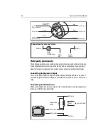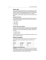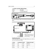
background image

Chapter 4: Commissioning the system

39

4.4 Testing and checks

Radar checks and alignment

Your E-Series display is part of an integrated system. Raymarine strongly advise that 
you test and align the radar 

before

 connecting to other systems.

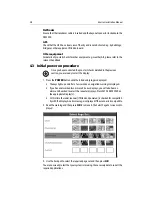
To test and align the radar you must first select a radar application. With the Select 
Page Set screen displayed (see previous section):

1. Press


OK

 to select the highlighted page set.

2. Press 

PAGE

. The currently selected page set is represented on the soft keys.

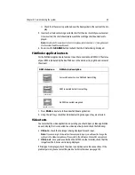
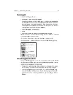
3. Press the corresponding soft key to display a full window radar application.
4. The scanner warm-up countdown commences. This will take 70 seconds (approx).

Note: 

If your scanner is incompatible, a message is displayed. If this is the case, you will be 

unable to proceed further with testing and aligning the radar. Refer to Important Informa-

tion - Radar Scanners at the front of this handbook.

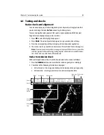
Radar transmission check

With a radar application active, check the transmission to the scanner as follows:

1. Press the 

RANGE

 button and ensure that the radar range adjusts accordingly.

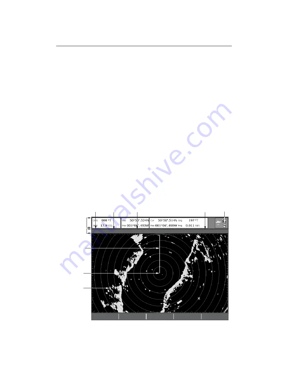
2. Check that all the following information is displayed:

• In the status bar - the range, orientation, motion mode and range ring spacing 
• In the data bar - a turning radar status icon and vessel position data.


3nm

Head-Up

Relative Motion

Rings  ½nm

VRM/EBL…

GAIN…

PRESENTATION…

TARGET

TRACKING…

TARGETS

DISPLAY…

D6803-2

Orientation

Data bar

Ship's
heading
marker

Radar status
icon

Range
ring

Boat's
position

Range

Motion mode

Range ring
spacing

Status bar

Содержание E120W

Страница 1: ...E Series Networked Display Installation Manual Document Number 87043_2 Date March 2006...

Страница 2: ...red in all major marketing territories AST Autoadapt Auto GST Autoseastate Autotrim Bidata Marine Intelligence Maxiview OnBoard Raychart Raynav Raypilot Raystar ST40 ST60 Seaclutter SmartRoute Tridata...

Страница 3: ...uld not be relied upon as a substitute for such prudence and judgement WARNING Product installation This equipment must be installed in accordance with the instructions in this handbook Failure to do...

Страница 4: ...e the SeaTalk High Speed blanking plug from the rear of the display until such time as you are ready to connect the cable Ensure that the SeaTalk High Speed cable is clicked into place AND then turned...

Страница 5: ...addition our policy of continuous product improvement may change specifications without notice Therefore Raymarine cannot accept liability for any differences between the product and the handbook Dis...

Страница 6: ...iv E Series Networked Display Installation Manual...

Страница 7: ...Scanners 11 Digital Sounder Module 11 Engines 11 Media storage cards 12 2 3 Functionality 12 Data or equipment required for applications functions 13 2 4 Integrating an E Series display 14 Single dis...

Страница 8: ...42 Chart application checks 42 Fishfinder application tests 43 Video tests 43 SeaTalkhsnetwork switch connection tests 44 Setting up the NMEA for AIS or Navtex 44 Instrument data tests 44 Running AIS...

Страница 9: ...R58194 Sun cover R58184 R58195 Cables all 1 5m Power NMEA 0183 SeaTalk Alarm out SeaTalk High Speed Network Video in composite cable R89005 R08004 E55054 E55049 E55057 Cable splice x3 For trunnion mou...

Страница 10: ...in 212 mm 8 3 8 in 252 mm 9 7 8 in D7206 2 182 mm 73 16 in clearance 154 mm 61 16 in Weight 4 18 kg 9lbs 3oz Note All imperial measurements are approximate PAGE ACTIVE WPTS MOB MENU DATA CANCEL OK RAN...

Страница 11: ...pares You can purchase the following spares Accessory item Part no Cables SeaTalk High Speed Network 1 5m SeaTalk High Speed Network 5m SeaTalk High Speed Network 10m SeaTalk High Speed Network 20m Se...

Страница 12: ...aysensurethemaximumseparationpossible between different items of electrical equipment For optimum EMC performance it is recommended that wherever possible Raymarine equipment and cables connected to i...

Страница 13: ...be sufficient space behind the display to allow cable connec tions to the rear panel connectors avoiding tight bends in the cables Interference Theselectedlocationshouldbefarenoughawayfromdevicesthat...

Страница 14: ...8 E Series Installation Manual...

Страница 15: ...Fast and accurate data transfer is achieved by using a combination of the following data protocols SeaTalk SeaTalk2 National Marine Electronics Association NMEA 0183 NMEA 2000 SeaTalk High Speed When...

Страница 16: ...ortant difference in that one cable will only carry information in one direction For this reason NMEA 0183 is generally used to connect a data receiver and a transmitter together e g a compass sensor...

Страница 17: ...marine dealer for full information Digital Sounder Module Important In order for your Digital Sounder Module DSM to be compatible with your E Series display you will need a DSM300 Part no E63049 Engin...

Страница 18: ...patibleinstrumentsusing CompactFlash cards To achievethe best results it is recommended that SAN DISK CF memory cards are used 2 3 Functionality For full functionality some applications require a dedi...

Страница 19: ...marine com for latest compatibility information 3 Whilst an AIS receiver is not required for the radar and chart applications to function thisreceiverisnecessaryifAISfunctionalityisrequiredwithinradar...

Страница 20: ...ies display OR ConnecttwoE SeriesdisplaysoranE SeriesdisplayandaDSM300viaacrossover coupler OR ConnecttwoormoreE SeriesdisplaysandaDSM300ifrequiredviaaSeaTalkHigh Speed switch to form a network The di...

Страница 21: ...t NMEA multiplexer Fast heading sensor RS232 interface Autopilot AIS receiver Navtex receiver To Video player Onboard camera DVD player To SeaTalk system Remote audible alarm RF ground earth PC via in...

Страница 22: ...you connect the master display to all other displays in the system via SeaTalk or SeaTalk2 you will negate the need to unplug and reconnect cabling if the master becomes unavailable The bridging of da...

Страница 23: ...alarm RF ground earth PC via interface box Third party equipment NMEA multiplexer Fast heading sensor RS232 interface Autopilot AIS receiver Navtex receiver Key Not supplied accessory Supplied Open ar...

Страница 24: ...player Onboard camera DVD player To VGA SVGA monitor Plasma screen M1500 monitor Power Cables Red 12V or 24V DC Black 0V Ground Earth RF Ground Key Not supplied accessory Supplied D8992 1 To AIS recei...

Страница 25: ...isplay Terminator Terminator SeaTalk2 cable ST290 DPU Existing SeaTalk 2 system Existing SeaTalk system SeaTalk 2 cable SeaTalk cable SeaTalk cable SeaTalk cable Power 12v supply SeaTalk2 Power RF gro...

Страница 26: ...20 E Series Installation Manual...

Страница 27: ...no hidden electrical wires or other items behind the selected location before proceeding Make sure there is sufficient rear access for mounting AND cabling The display unit is waterproof to CFR 46 and...

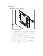
Страница 28: ...It is suggested that you use your thumb or forefinger in a circular motion to do this 5 Attach the display unit into the trunnion bracket adjustingtheunit to therequired angle for clear vision 6 Tight...

Страница 29: ...ut out line 5 Ensurethattheunitfitsintotheareathathasbeencutoutandthenfilearoundthe cut edge until smooth 6 Drill four 4 5mm 1 8 inchapprox holes asindicatedon the template to accept the securing bolt...

Страница 30: ...splay ensuring that the locking lugs located at the bottom edge of the covers are latched into position 3 Ensure that the control buttons pass through their respective openings 4 Apply firm but even p...

Страница 31: ...g a flat bladed screwdriver placed in the aperture at the top right of the front cover clip on gently twist it to release the top clips 3 Workingfromthiscorner freetheclipsalong thetopedgeof thedispla...

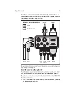
Страница 32: ...nd tie it out of the way Do notremovetheSeaTalkHighSpeed blanking plug fromtherearofthe display untilsuch time as you are ready to connect the cable Failure to adhere to this may result in the ingress...

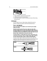
Страница 33: ...use the cable splicers The cable splicers are used to make the connections from the SeaTalk Alarm out and NMEA 0183 cables easy and secure without removing insulation from cable tails Note Do not use...

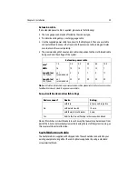
Страница 34: ...ing switch or at a DC power distribution panel Raymarine recommends that power is fed directly to the display and scanner via its own dedicated cable system and MUST be protected by a thermal circuit...

Страница 35: ...duct pageson our website Fuse circuit breaker and switch ratings Do not fit switches or circuit breakers in such a way that power may be removed from part of the E Series networked system while leavin...

Страница 36: ...24 volts If you need a higher current or voltage you should connect the E Series via an external relay Connecting an inductive load When connecting the output to a relay or other inductive device a sp...

Страница 37: ...display until such time as you are ready to connect the cable When inserting the cable ensure that it is clicked AND then turned in order to lock it into place and create a watertight connection How t...

Страница 38: ...deosourcetype youwillneedtopurchaseanS Videocable Part no E55062 Youcanconnect2inputsusingS videotoeachE SeriesDisplay Thecolor of each connector defines the video number to which it configures within...

Страница 39: ...edintoseparateESeries units on the same network Note Please refer to page 5 for details ofthis accessory SeaTalk2 not supplied Use this cable to connect to third party equipment or SeaTalk2 instrument...

Страница 40: ...ats DC Power Supply E Series Display Power to display Power to open array Split pedestal cable 15 or 25 metres Note The power supply for both the display and the open array must be of the same voltage...

Страница 41: ...th Weight Radome power output E55065 15m Heavy 2Kw or 4 Kw E55066 25m Heavy 2Kw or 4 Kw E55067 10m Light 2kw E55068 15m Light 2kw Pedestal adaptor cable D7327 1 To display To open array connector To p...

Страница 42: ...36 E Series Installation Manual If the existing cable is too short please order from the following RANGE CANCEL OK PAGE ACTIVE WPTS MOB MENU DATA IN OUT Display Boats DC Power Supply D6619 2 Radome...

Страница 43: ...curing bolts should be fully tightened and any mechanical locking arrangements as specified are in place Ensure scanner and power connections have been made If an open array is fitted ensure that powe...

Страница 44: ...s the POWER button until the introductory logo is displayed The keys light up and after a few seconds a navigation warning is displayed If you have networked two or more E Series displays you will als...

Страница 45: ...rox Note Ifyourscannerisincompatible amessageisdisplayed Ifthisisthecase youwillbe unable to proceed further withtesting and aligningthe radar Refer to Important Informa tion Radar Scanners at the fro...

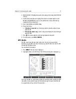
Страница 46: ...ing from the target visual bearing these examples may help 3 From the primary radar soft keys press VRM EBL 4 ToggletheVRM EBLsoftkeytoON AdjusttheEBLtoyourchosentarget Ifthereis a difference between...

Страница 47: ...t is adjusted 8 To exit the menu press OK or CANCEL GPS checks The GPS is used to position your boat on the chart You can set up your Global Positioning System GPS and check its status using the GPS s...

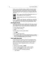
Страница 48: ...data bar If heading data is not available your display can use COG data This will however affect the operation of the following functions overlay a radar image over your chart orientate a radar image...

Страница 49: ...at individual settings change as they are selected Video tests To ensure that the video application is operating you should open a video application on each display that is connected to a video input...

Страница 50: ...d to change the NMEA Port Setting This feature is accessed via the System Setup Menu System Integration Setup Menu You can connect either AIS or Navtex or other instrument to one display In multiple d...

Страница 51: ...specify the 38 400 baud rate for the NMEA port that communicates with the AIS transceivers and receivers see the table on page 44 Weather application tests TotestyourWeatherapplicationcreateandopenawe...

Страница 52: ...parameter you wish to adjust Thesoft key label is highlighted 6 Use the rotary control to adjust the parameter value in the box above the soft key 7 Press OK or use the rotary end push to accept the a...

Страница 53: ...cture locate a straight dock seawall or bridge that is facing your boat If the image is bent or bowed the display timing will need adjustment Under certain circumstances it may be easier to adjust the...

Страница 54: ...48 E Series Installation Manual...

Страница 55: ...k power supply cable issound and that all connections are tight and free from corrosion Check relevant fuses Check power source is of the correct voltage and sufficient current My display switches off...

Страница 56: ...to the world wide web contact Technical Support where specialists are available to answer questions about installing operating and trouble shooting all Raymarine products Help us to help you When req...

Страница 57: ...rn Standard Time or Eastern Daylight Savings Time If you are not sure which item is appropriate for your unit you should first contact the Technical Support Department to verify your requirements 1 80...

Страница 58: ...uireabout therepairstatusofyourunit contacttheRepairCenter at 1 800 539 5539 How can I contact Raymarine in Europe You can obtain Technical Support service and accessories from your authorized Raymari...

Отзывы: