


The transducer position will be adjusted further during testing
(see
Testing the transducer
).
D
12639-1
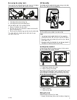
12. Tighten the transducer pivot bolt.
13. Tighten the kick-up adjustment screw to achieve the desired
kick-up force.
The kick-up force needs to be adequate to prevent the
transducer from kicking-up during testing but also needs to
be loose enough so that it can kick-up should the transducer
be struck by an object when underway.
Note:
The third locking screw is not used until the transducer
has been successfully tested.
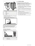
4.2 Cradle mounting
Follow the steps below to mount the display’s cradle.
Before mounting ensure that you have:
• selected a suitable location.
• installed the transducer and routed the power/transducer
cable to the selected display location.
00
0
0
D12630-2
0
0
0
0
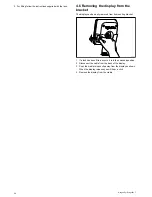
1. Mark the location of the cradle base’s screw holes on the
chosen mounting surface.
2. Drill holes for the screws using a suitable drill, ensuring there
is nothing behind the surface that may be damaged.
3. Use the 3 screws supplied to attach the cradle base securely
to the mounting surface.
4. Attach the display cradle to the base.
5. Tighten the centre screw to secure the display cradle to the
base.
Note:
The appropriate torque to use when drilling depends on
the thickness of the mounting surface and the type of material.
Mounting
25
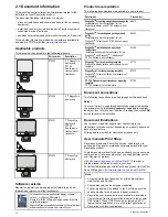
Содержание Dragonfly
Страница 2: ......
Страница 4: ......
Страница 10: ...10 Dragonfly Dragonfly 7...
Страница 14: ...14 Dragonfly Dragonfly 7...
Страница 34: ...34 Dragonfly Dragonfly 7...
Страница 66: ...66 Dragonfly Dragonfly 7...
Страница 78: ...78 Dragonfly Dragonfly 7...
Страница 90: ...90 Dragonfly Dragonfly 7...
Страница 97: ...Chapter 15 Technical support Chapter contents 15 1 Raymarine customer support on page 98 Technical support 97...
Страница 102: ...102 Dragonfly Dragonfly 7...
Страница 103: ...Chapter 17 Spares and accessories Chapter contents 17 1 Accessories on page 104 Spares and accessories 103...
Страница 105: ......
Страница 106: ...www raymarine com...


