4 INSTALLATION
© 2022 RAYLASE GmbH SUPERSCAN IV
MN105-en / v1.0.12
34
4.6.1
Standard installation
1.
Fit the prepared aligning pins into the corresponding holes in the installation surface.
2.
Carefully remove the protective cover on the deflection unit beam input.
3.
Position the deflection unit on the installation surface using the pins.
4.
Secure the deflection unit with the prepared screws.
The deflection unit is aligned with the laser system beam output using the pin holes.
If the deflection unit has a water cooling option, connect the cooling water to the deflection unit. Pay
attention to page 31, Requirements for cooling water.
Complete the installation according to chapter 4.7.
4.6.2
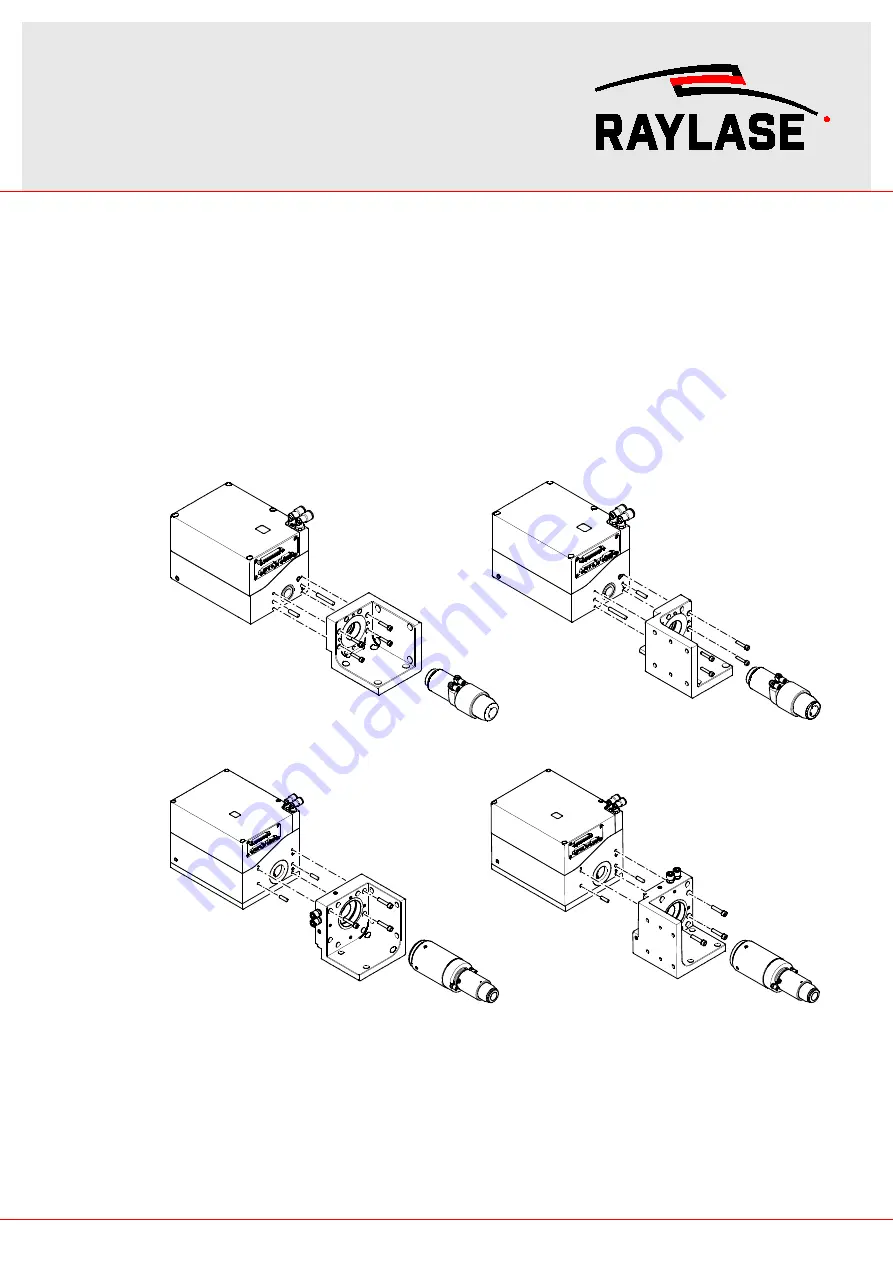
Installation with Collimator Bracket Set
Fig. 16: Installation options SUPERSCAN IV-15 with Collimator Bracket Set 002 and D25 collimator
Fig. 17: Installation options SUPERSCAN IV-30 with Collimator Bracket Set 001 and D50 collimator
1.
Fit the prepared aligning pins into the corresponding holes in the installation surface used for
mounting the collimator bracket.
2.
Position the collimator bracket on the installation surface using the pins.
3.
Secure the collimator bracket with the four prepared screws.
4.
Fit the aligning pins which are included in the Collimator Bracket Set into the collimator bracket
according to the figures above.
5.
Carefully remove the protective cover on the deflection unit beam input.


