10
CVS-21HA.rev.03
CONNECTING THE PROBES
To extend the probes:
Each probe can be extended up to 500 ft (150 m). To extend a probe:
Use a shielded cable with an outside diameter between 0.245
and 0.260 in (6.22 and 6.60 mm) (the cable dimension must not be
under 18 AWG) to ensure the cable entry is liquid-tight. Do not
ground the shielding.
It is preferable to solder the cable joint to ensure a proper contact
between the two cables.
CAUTION:
Do not run probe cables next to other power cables. When
crossing over other cables, cross at 90°.
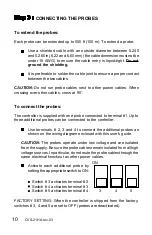
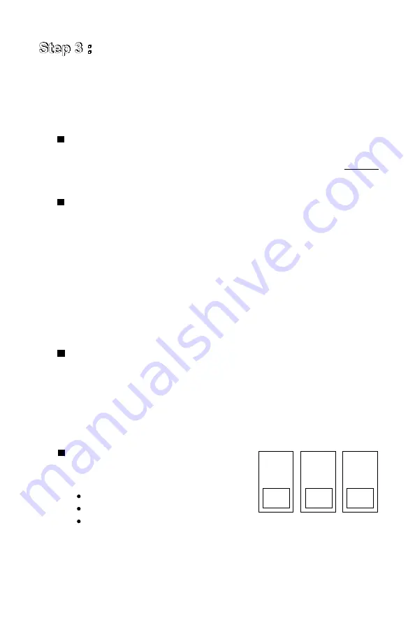
Activate each additional probe by
setting the appropriate switch to ON:
Switch # 3 activates terminal # 2.
Switch # 4 activates terminal # 3.
Switch # 5 activates terminal # 4.
FACTORY SETTING: When the controller is shipped from the factory,
switches # 3, 4 and 5 are set to OFF (probes are deactivated).
To connect the probes:
The controller is supplied with one probe connected to terminal #1. Up to
three additional probes can be connected to the controller.
Use terminals # 2, 3 and 4 to connect the additional probes as
shown on the wiring diagram enclosed with this user's guide.
CAUTION: The probes operate under low voltage and are isolated
from the supply. Be sure the probe cables remain isolated from all high
voltage sources. In particular, do not route the probe cables through the
same electrical knockout as other power cables.
3
ON
4
5

