background image

55M4000EBE00  Rev C

34

i4000 Lattice Crane

Instruction Manual

4.4  System in configuration mode

This allows the operator to personalize his system. Namely, the display language, the measuring 

unit, the light intensity of the graphic display, the date and time.

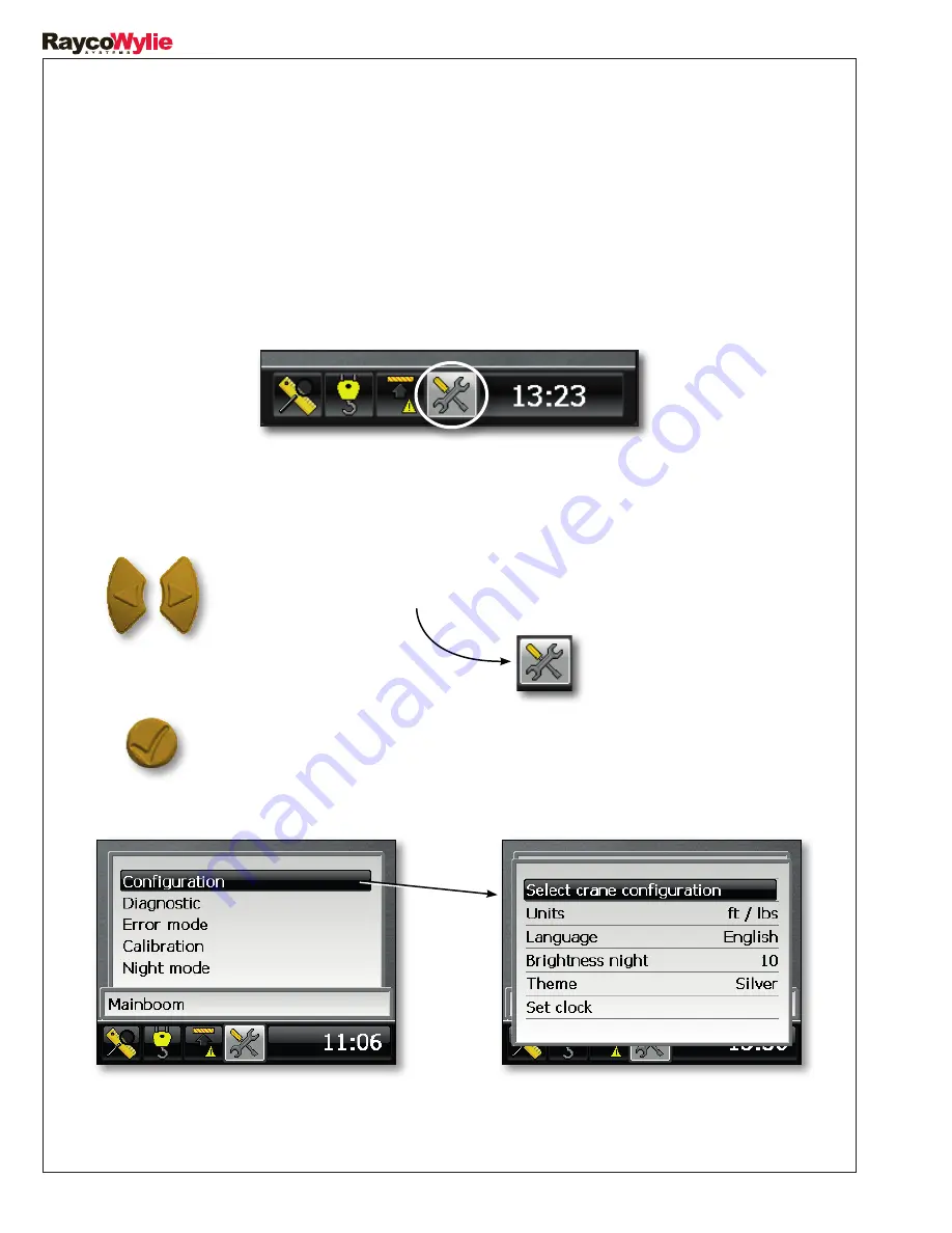
4.4.1  Access the Configuration menu

You need to be in operating mode (main screen). The lower part of the screen should look 

like this:

1.  Navigate to the Tools tab with the LEFT or RIGHT keys. 

2.  Press the  ‘ENTER’ key to access the configuration options.

Now you can choose the option you wish to configure.

The screen may vary depending on the sensors which are activated. E.g., if a rotation sensor is 

installed, the ‘Range limiting device’ will be present.

Содержание i4000

Страница 1: ...8 266 6610 Rayco Electronic Systems Rayco Technology Group 2440 Dalton Avenue Ste Foy Qc CANADA G1P 3X1 Tel 1 418 266 6600 Fax 1 418 266 6610 Wylie Systems Rayco Technology Group Drury Lane St Leonards on Sea East Sussex ENGLAND TN38 9BA Tel 44 0 1424 421235 Fax 44 0 1424 433760 55M4000EBE00 Rev C Crane Warning Systems Atlanta 6175 Hickory Flat Hwy Suite 110 376 Canton GA 30115 877 672 2951 Toll F...

Страница 2: ......

Страница 3: ......

Страница 4: ......

Страница 5: ...he operator When the parameters are correctly set the indicator warns the crane operator of a potential overload which could endanger the equipment or the goods and cause injuries to the operator or the workers who are close to the crane and its load This system must not be used as a substitute for the operator s sound judgement while performing tasks with the lifting equipment The operator is res...

Страница 6: ......

Страница 7: ...erator s safety or the machinery s integrity are concerned Please take your time to read and understand these definitions NOTE PROVIDES INFORMATION WHICH CAN BE OF SPECIAL INTEREST DANGER INDICATES A POTENTIALLY DANGEROUS SITUATION WHICH IF NOT AVOIDED COULD RESULT IN A PERSON S DEATH OR IN SIGNIFICANT DAMAGE TO THE MACHINERY ATTENTION INDICATES A POTENTIALLY DANGEROUS SITUATION WHICH IF NOT AVOID...

Страница 8: ......

Страница 9: ... 1 7 Technical information page 18 2 DETAILED DESCRIPTION OF THE DISPLAY UNIT page 19 2 1 Navigating the normal mode of operation page 19 2 2 Indicator tab page 20 2 3 Load tab page 21 2 4 Range limiting device tab page 22 2 5 Tools tab page 22 2 6 Overview of the display unit page 23 2 7 Description of operation keys page 24 2 8 Warning lights and messages page 25 2 8 1 Overload warnings page 26 ...

Страница 10: ...t s parameters page 41 4 5 3 1 Maximum load allowed page 41 4 5 3 2 Number of parts of line page 42 4 5 4 Defining or removing the zero setting mode tare page 43 4 5 5 Bypassing a lockout page 44 4 6 System in ABSOLUTE LIMITING mode page 46 4 6 1 Accessing the absolute limiting adjustment mode page 47 4 6 2 Activating or deactivating an absolute limit page 47 4 6 3 Adjusting an absolute limit valu...

Страница 11: ...or page 61 5 4 Detected addresses page 61 5 5 Error messages page 62 5 5 1 Internal peripherals page 62 5 5 2 External peripherals page 63 6 INSPECTION AND MAINTENANCE page 66 6 1 Frequent inspections page 66 6 2 Periodic inspections page 66 6 3 Checking the displayed load page 67 6 4 Maintenance page 68 6 5 Maintenance procedure page 69 6 6 Adjustments and repairs page 70 ...

Страница 12: ......

Страница 13: ...e consider each safety directive mentioned in this manual when using the i4000 system This manual will help qualified personnel use the system and perform its maintenance 1 1 Introduction The i4000 system shall be operated only by personnel without limitations in the physical abilities of the upper limbs and no visual or hearing impairment who have completed all operator trainee qualification requ...

Страница 14: ... options are included the system uses the information provided by the sensors to calculate the operational radius allowing the operator to assess the crane s current capacity and to verify the overload conditions A rotation sensor optional can also be installed to measure the boom position within 360 degrees and provide the operator with additional information The system display is located inside ...

Страница 15: ...ght turns red when 100 of the nominal capacity is reached or exceeded This light is green under normal operating conditions 1 4 1 Audible alarm An intermittent audible alarm within the display unit warns the crane operator that an intervention is necessary before the load reaches its nominal value The default threshold for the approaching alarm is 90 of the nominal capacity The overload alarm is a...

Страница 16: ...d output devices controlled by the i4000 system optional 3 Load sensor A load sensor is used in order to calculate the load on the hook It is generally integrated into a dynamometer installed on the lifting rope 4 Angle sensor An angle sensor is used in order to measure the boom angle 5 Limit switch A2B The limit switch helps to prevent the pulley block from colliding with the boom head pulley opt...

Страница 17: ...17 i4000 Lattice Crane Instruction Manual 55M4000EBE00 Rev C 1 6 Overall scheme ...

Страница 18: ...C to 60 C Power supply 9 32 VDC maximum power supply Display unit dimensions 3 5 Crystal liquid screen 320 x 240 Display unit protection IP67 Bus CAN interface sensors Default quantity Maximum quantity Load or pressure sensors 1 2 Angle or length sensors 1 1 Relay output 1 1 Rotation sensor 1 1 Possibility of additional sensors YES Radio Module 0 1 ...

Страница 19: ...he normal mode of operation of the i4000 system is organized into four separate screens We call it tabs Use the left or right arrow keys to navigate in these tabs There are 1 the indicator tab 2 the load tab 3 the range limiting tab 4 the tools tab INDICATOR TAB LOAD TAB RANGE LIMITING TAB TOOLS TAB USE THE LEFT OR RIGHT ARROW BUTTONS TO CHANGE TABS ...

Страница 20: ...ht should only be used as a guide and NOT as an indicator of whether the crane may pass or not underneath a structure whose exact height is known 2 2 Indicator tab It allows the display of multiple sensors providing a good overview of the crane during operation RADIUS SLEW ANGLE BOOM ANGLE BOOM LENGTH PARTS OF LINE BOOM TIP HEIGHT ALARMS WEIGHT ON HOOK MAIN OR AUXILIARY AUX BOOM ...

Страница 21: ...IGHT ON THE HOOK NOMINAL MAX LOAD CAPACITY PERCENTAGE OF THE LOAD CAPACITY 2 3 Load tab The Load tab will only be shown if a load interface is activated LED lit TARE is activated For a more detailed display of everything concerning the load to be lifted The hoist the number of strands and the maximum capacity are adjusted under this tab ...

Страница 22: ...G ZONE CEILING For viewing all the information about the programmed limit Limits are removed or added under this tab 2 5 Tools tab CURRENT CRANE CONFIGURATION Under the tools tab you will find among others the diagnostic mode the error mode the calibration mode and the day night display mode The parameter indicating the boom tip height should only be used as a guide and NOT as an indicator of whet...

Страница 23: ... PAD WITH CONFIRM AND ESCAPE BUTTONS WARNING LIGHT 3 COLORS INTEGRATED AUDIBLE INDICATOR GRAPHICAL DISPLAY WARNING LIGHT Under normal working conditions the light is green The light turns yellow to indicate the approach to a preset operating limit The light turns red to warn the operator of any abnormality ...

Страница 24: ...ress this key to leave a menu or settings window and to return to the previous screen without saving the changes Press several times to return to the main menu RIGHT KEY Press this key to scroll right through the tabs of the main menu or in editing mode to move on to the next digit of a configurable value LEFT KEY Press this key to scroll left through the tabs of the main menu or in Edit mode to r...

Страница 25: ...NE RADIUS OPERATING ZONE CEILING RANGE LIMITING DEVICE ABSOLUTE LIMITING DEVICE APPROACH REACHED APPROACH REACHED WARNING LIGHT GREEN NORMAL YELLOW FLASHING OVERLOAD OR LIMIT APPROACH RED A2B OVERLOAD OR LIMIT REACHED RED FLASHING BYPASS ACTIVATED ANTI TWO BLOCK A2B CONDITION DETECTED MAXIMUM LOAD LIMITED BY THE ROPE CAPACITY LOAD TAB INDICATORS ...

Страница 26: ...city has been reached or exceeded The red REACHED signal lights up when the load on the hook is equal or more than 100 of the nominal capacity adjustable value The warning light turns red The audible alarm sounds continuously 2 8 1 Overload warnings A warning message will be displayed in the range limiting tab in order to inform the operator that a load limit has been reached INDICATOR TAB Flashin...

Страница 27: ...pears on the screen of the i4000 system to indicate that the allowed nominal load is limited by the rope s safe operation limit Increase the number of strands parts of line between the head pulley and the pulley block and change the number of strands on the i4000 system to turn off this indicator and thus increase the crane s nominal capacity A warning message will be displayed on the other tabs I...

Страница 28: ......

Страница 29: ...in compliance with Raycowylie instructions using only Raycowylie components supplied with the system Installation and calibration manuals are available upon request from RaycoWylie Please note that the calibration and installation instructions have been intentionally left out of this manual A bad calibration of the system can cause an overload which could damage the machine breaking the structure ...

Страница 30: ......

Страница 31: ...not necessarily prevent damages to the machine due to an overload or other causes 3 The proper functioning of the equipment depends on a daily inspection and on compliance with this manual s operating instructions 4 The crane should always be operated smoothly and at a safe speed 5 In order to have an adequate work radius the system must be correctly configured A wrong configuration may generate a...

Страница 32: ...he presence of electric wires in the crane s work zone The machine may therefore work close to and come in contact with undetected electric wires which may cause serious injuries or even death The system does not indicate if the stabilizers have completely come out This may increase the risk of the machine breaking or tilting thus causing injuries and even death The system does not indicate the cr...

Страница 33: ...system is ready to be used If there is at least one jib activated on the i4000 the system will present the current configuration The crane operator must now confirm the configuration proposed by the system by selecting Yes or choose another configuration by selecting No Once he has chosen a configuration the i4000 system switches to its normal operating mode If a limit has been set up and it has n...

Страница 34: ... time 4 4 1 Access the Configuration menu You need to be in operating mode main screen The lower part of the screen should look like this 1 Navigate to the Tools tab with the LEFT or RIGHT keys 2 Press the ENTER key to access the configuration options Now you can choose the option you wish to configure The screen may vary depending on the sensors which are activated E g if a rotation sensor is ins...

Страница 35: ...ay He can choose either METRIC m kg m te or IMPERIAL ft lbs ft Tons ft long Tons ft klbs 1 Access the Configuration menu see section 4 4 1 2 Scroll vertically to the Units menu with the UP DOWN keys 3 Press ENTER to change the unit 4 Choose the desired unit using the UP DOWN keys 5 Press ENTER again to save the unit Or press the ESCAPE key to quit without saving the changes ...

Страница 36: ...n the system will be displayed The default language is English 1 Access the Configuration menu see section 4 4 1 2 Scroll vertically to the Language menu with the UP DOWN keys 3 Press ENTER again to change the language 5 Press ENTER again to save the language Or press the ESCAPE key to quit without saving the changes 4 Choose the desired language using the UP DOWN keys ...

Страница 37: ...ensity 1 Access the Configuration menu see section 4 4 1 2 Scroll vertically to the Brightness night menu with the UP DOWN keys 3 Press ENTER to change the 3 digits 4 Change the first digit by entering your desired value using the UP DOWN keys 5 Then press the ENTER key again to move to the following digit Repeat steps 3 and 4 for the following digits After entering the last digit press ENTER to s...

Страница 38: ... 1 6 Change the first digit by entering your desired value using the UP DOWN keys Next press ENTER to move to the second digit Repeat step 5 for the following digits After entering the last digit press ENTER to save the value 2 Scroll vertically to the Set clock menu with the UP DOWN keys 3 Press ENTER again to access the menu The following menu will appear 4 Scroll vertically to the item you wish...

Страница 39: ... Navigate to the Tools tab with the LEFT RIGHT keys to view the current crane configuration on the lower part of the screen This allows the operator to choose the type of attachments mounted on the crane This is very important since the calculation of the radius depends on it In turn the maximum load lifted by the operator will depend on the radius TOOLS TAB The i4000 is not a Rated Capacity Indic...

Страница 40: ...ess the ESCAPE key to quit without saving the changes 1 In the main mode operating mode select the Load tab using the LEFT RIGHT keys 2 Press ENTER to view the lifting hoist parameters menu 1 To change the configuration go to the item Configuration and press ENTER 2 Scroll vertically to the Select crane configuration menu with the UP DOWN keys 3 Press ENTER to access the menu 4 5 System in lifting...

Страница 41: ...elected either the main hoist or the auxiliary hoist you can change its parameters These are the maximum load allowed maximum capacity authorized by the crane manufacturer and the number of parts of line 4 5 3 1 Maximum load allowed The lifted load is always compared to this value in order to warn the operator when he approaches or reaches an overload and to apply a motion cut if necessary Use the...

Страница 42: ...he previous digit Press the RIGHT key to go to the next digit At any time press the ESCAPE key to go back without saving changes 4 5 3 2 Number of parts of line The number of parts of line is used for load calculation and it helps to assess the allowed lifting limit of the rope A indicator will lights up if the maximum load is limited by the rope s capacity 1 In the main mode operating mode select...

Страница 43: ... to save the value 2 Press ENTER to view the lifting hoist parameters menu 4 5 System in lifting mode cont 4 5 3 2 Number of parts of line cont 4 5 4 Defining or removing the zero setting mode Tare A YELLOW LIGHT INDICATES THAT THE TARE IS ACTIVATED SOME WEIGHT HAVE BEEN REMOVED FROM THE CALCULATED LOAD Select the tare mode option to display the actual load on hook during a lifting operation This ...

Страница 44: ... menu 3 Scroll to the Set tare load line using the UP DOWN keys 4 Press ENTER to activate the zero setting function The line will then change to Clear tare load 4 5 System in lifting mode cont 4 5 4 Defining or removing the zero setting mode cont 4 5 5 Bypassing a lockout Be Careful The i4000 does not support the rigging mode In this situation the crane is not entirely protected by the i4000 and i...

Страница 45: ...s after it has been set or When no brake measure is applied or There is a faulty sensor or An A2B situation comes up or The i4000 system restarts When the lockout system is bypassed during an overload situation the RED warning signal flashes The audible alarm is silent A bypass message is alternately displayed on screen The operator can bypass the lockout system in case of an emergency by pressing...

Страница 46: ...mum boom length limit 4 The maximum boom head height limit 5 The maximum work radius limit Please make sure you have read and understood these instructions before defining the operational limits A wrong setting of operational limits can lead the machine to collide with obstacles and thus cause serious injuries or death Important Please note that no brake measures are applied on absolute limits Abs...

Страница 47: ...light the Set absolute limits line 3 Press ENTER to confirm your choice and access the adjustment mode 4 Press ENTER at the Select limit line then press the UP DOWN keys to choose the limit you wish to adjust 1 Use the UP DOWN keys to highlight the Limit enabled line 2 Press ENTER to edit the value Press the UP DOWN keys to choose between On Off active inactive INDICATOR TAB 5 Press ENTER to confi...

Страница 48: ... ENTER to confirm your choice 4 Scroll down to the Set value line then press ENTER 5 Change the first digit by entering your desired value using the UP DOWN keys 6 Press ENTER to move to the second digit 7 Repeat steps 5 and 6 for the following digits After entering the last digit press ENTER again to save the value Press the LEFT key to go back to the previous digit Press the RIGHT key to go to t...

Страница 49: ...ractice which calls for additional precautions To prevent the risk of electrocution it is therefore essential to operate the crane outside of the minimum distances authorized so that there is no possibility that the crane the lifting rope or the load become an electrically conductive path The crane should never be used to move around the material stored under power lines except if a combination of...

Страница 50: ...tion When a rotation sensor is installed on the crane and the Range limiting device of the i4000 system is activated a new tab will appear on the selection bar HEIGHT LIMIT RIGHT WALL LIMIT RADIUS LIMIT LEFT WALL LIMIT RANGE LIMITING TAB 4 7 2 Accessing the range limiting adjustment menu The yellow bar shows the moving boom position A yellow arrow indicates an approaching limit A red arrow indicat...

Страница 51: ...elect button to confirm your choice 4 Boom up to the desired boom tip height limit 5 Press the Select button to confirm the maximum boom tip height position 6 As you release the Select button a 10 seconds countdown will allow you to boom down before your programmed height limit becomes active Height limit programmed RED ZONE 4 7 3 Height Limit The height limit is the maximum boom tip height desire...

Страница 52: ...wall 5 Press ENTER to confirm the position of the first wall 6 Turn the crane and establish the position of the second limit second wall 7 Press ENTER to confirm the position of the second wall After you release the key you will have a 10 second countdown to pivot the crane between both walls before your programmed limit is activated 52 The free zone is a zone without height limit The free zone is...

Страница 53: ...he Select button to confirm your choice 4 7 5 Variable height limit 4 7 4 Free zone cont PROGRAMMED FREE ZONE Right wall reached Left wall reached LEFT WALL RIGHT WALL A variable height limit is a height limit which can vary in function of the rotation of the boom variable ceiling Depending on the configuration of the obstacle it may be necessary to limit to a certain height for a position and at ...

Страница 54: ...o return between the two walls and boom down before your programmed Variable Height Limit becomes active 6 Rotate the crane toward the second limit position second wall with the boom tip always at the maximum height permitted by the surrounding environment 5 Press the Select button to confirm the position of your first limit 7 Press Select button to confirm the position of the second wall LEFT WAL...

Страница 55: ...y to limit to a certain radius for a position and another radius for another position 1 When in the range limiting tab press the ENTER key to access the range limiting adjustment menu 2 Scroll up or down to highlight the Set variable limit radius line 3 Press the Select button to confirm your choice 4 Rotate the crane until you reach the position of your first limit first wall 5 Press the Select b...

Страница 56: ...m tip always at the maximum radius permitted by the surrounding environment 8 As you release the Select button a 10 seconds countdown will allow you to return between the two walls and boom up within the allowed radius limit before your programmed Variable Radius Limit becomes active 7 Press Select button to confirm the position of the second wall Left wall reached Right wall reached Restricted ar...

Страница 57: ......

Страница 58: ...the i4000 system To access the diagnostic menu Warning Maintenance must be performed by a qualified technician or by an operator aided by a RaycoWylie technician 5 Diagnostic and maintenance A diagnostic menu provides information on the system status as well as on the status of all the connected sensors 1 Navigate to the Tools tab with the LEFT or RIGHT keys 3 Press the ENTER key to access the dia...

Страница 59: ...Each line in the diagnostic menu will open up another page when you select it and press ENTER Each page deals with a specific type of sensor or a particular type of information Independently of the system configuration the following 2 pages are always accessible Addresses detected and System Additional pages are optional and they are only visible if one or several sensors are activated refer to th...

Страница 60: ...sor In case of an angle sensor multifunction take note of these values and report them to a RaycoWylie Systems technician Press ENTER when Angle 1 is highlighted to view the name and version of the angle sensor software as well as its calibration status The information shown will look like this Press ESCAPE to go back to the main screen of the diagnostic mode ...

Страница 61: ...sic criteria for a proper functioning of the load sensor The value of the Scale factor must be less than 1 0 Dr must be close to 5 00 DC volts Press ESCAPE to go back to the main screen of the diagnostic mode 5 4 Detected addresses This page of the diagnostic menu displays the addresses of the different sensors on the bus CAN network detected by the i4000 system The addresses remain in the memory ...

Страница 62: ... Contact the RaycoWylie technical assistance department Bus Off Verification of the bus CAN controller 1 There is a physical problem on the CAN network Contact the RaycoWylie technical assistance department Calib parameter The crane s dimensions must be correctly entered otherwise the load value could be null or wrong The value of variables CL1 CL2 and CL2MR should never be zero At power up and du...

Страница 63: ...nal in volts is not valid 1 to 4 volts 1 The 12 bit converter or accelerometer is faulty Angle 1 In prod Cal Indicates that the angle interface is in pre calibration mode Angle 1 Lost communication The system has not received a valid message from the Angle interface within the required time frame 1 The Angle interface is faulty 2 The cable linking the interface to the bus CAN network is broken Ang...

Страница 64: ...received a valid message from the Load interface within the required time frame 1 The Load interface is faulty 2 The cable linking the interface to the bus CAN network is broken Error message Runtime process Error cause Relay 1 Lost communication The system has not received a valid message from the relay interface within the required time frame 1 The relay interface is faulty 2 The cable linking t...

Страница 65: ...1939 error Absolute rotation same position kept at all times Error message Runtime process Error cause Rotation 1 Ratio not set The system detects a ratio of 0 No ratio has been entered or calibrated Rotation 1 Lost communication The system has not received a valid message from the rotation interface within the required time frame 1 The rotation interface is faulty 2 The cable linking the interfac...

Страница 66: ...ns and maintenance When you switch on the system check if all the alarm lights audible alarms and lockout are working Make sure the system is correctly configured Check the accuracy of the clock Make sure the system has not detected any errors Check the weight on the hook it should be the same as the last time you checked Check the radius according to the boom selection The radius displayed should...

Страница 67: ... capacity close to the minimum radius should be used to test the alarm and the load indicator s accuracy Rig with enough strands to lift a significant load Measure and enter the radius and the load on the hook Record the radius load on hook and number of strands on the display unit s screen Lift the load Enter the current weight including the hook and the rigging accessories Record the average max...

Страница 68: ...eplace the A2B switches if the piston is too corroded 6 4 Maintenance Unless otherwise specified by a RaycoWylie technician all original and replacement parts must be provided by RaycoWylie In order to ensure that the i4000 display is water resistant make sure the back has an X shaped tightening Your i4000 system does not need any additional lubrication Important If you see condensation forming in...

Страница 69: ...ease the hydraulic pressure of all hydraulic circuits before releasing or lifting the hydraulic components A Danger or Broken sign should be placed on the crane commands to be removed only by authorized personnel Once the adjustments and repairs are finished the crane should still not be used until all the safety devices have been activated and the air released from the hydraulic system The instru...

Страница 70: ...ments and repairs If you have any questions or need assistance please contact our technical assistance department Have your i4000 system s serial number handy All adjustments should be made in compliance with the tolerated values specified by RaycoWylie in order to keep each system component in proper working condition If you need spare parts to complete the maintenance or repairs please contact t...

Страница 71: ...71 i4000 Lattice Crane Instruction Manual 55M4000EBE00 Rev C Notes ...

Страница 72: ......

Отзывы: