Raychem 920 Series Скачать руководство пользователя страница 5

nVent.com  

|

  5

SECTION 1 OVERVIEW

1.1 INTRODUCTION

This manual provides information pertaining to the installation and operation of the 

RAYCHEM 920 Series Heat Trace Controller Operator Console. For information relating to 

the programming, installation maintenance and troubleshooting of other 920 Series products, 

including the Dual Point Control Module, Controller Assemblies, etc., please refer to the 

920 Series Controller Manual.
Additional copies of this manual may be ordered separately through your nearest sales office 

using the order number listed on the front cover.

1.2 CONTROLLERS COVERED BY THIS MANUAL

This document covers the 920 Series Heat Trace Controller Operator Console. The information 

coincides with the specific releases of firmware for the 920 product which are listed on the 

front page. As nVent releases new firmware to modify or enhance the product significantly, 

new documentation will accompany these releases. To ensure that you are using the correct 

documentation for your particular version of controller, please check the firmware version 

number of the 920 against the version number listed on the front of this manual. This may be 

displayed using the 920 Series Operator Console or a communicating device. As subsequent 

changes are made, updates will be included in manuals shipped after the firmware is released.  

If issued, supplements will make specific reference to any operational or functional changes.

1.3 PRODUCT OVERVIEW

1.3.1 Description

The 920 Series Operator Console provides a simple, easy to use interface to the Dual Point 

Controller, alleviating the need for a communicating device to configure the Controller. The 

Console allows you to look at or reset alarms, test or monitor the heat tracing, and examine or 

alter the configuration.
The Console may be left installed permanently or may be installed temporarily for display/

setup during maintenance and troubleshooting. Access is available for all monitored 

parameters, programmed values, and alarm information. Enhanced security is provided by 

password protection.
The unique design of the Operator Console allows it to be installed or removed under power 

even in hazardous areas.
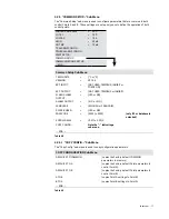
1.3.2 Features

Keypad and Alpha-numeric Display
A six character alpha-numeric LED display provides the operator with large easy to read 

messages and prompts, eliminating complex and cryptic programming. Six individual keys are 

provided to quickly access alarming and operational information.
–40 to 140°F (–40 to 60°C) Operation
Extended temperature operation permits installation in all but the harshest environments.
CSA C/US & FM Approved 
The 920 Series Operator Console is approved for Class I, Division II, Groups A,B,C,D and Zone 2 

hazardous locations making it ideal for direct use in the field.

1.4 ORDERING INFORMATION

The 920 Series Operator Console is ordered as a separate item from the Controller Assembly 

or other components. It may be ordered as Model #920CON. Please refer to the latest 

RAYCHEM 920 Series Ordering Guide for additional information.

IMPORTANT WARNINGS AND NOTES

The following icons are used extensively throughout this manual to alert you to important warnings 

 that affect safety and to important notes   that affect the proper operation of the unit.

Be sure to read and follow them carefully.

Содержание 920 Series

Страница 1: ...ctions 920 SERIES HEAT TRACE CONTROLLER OPERATOR CONSOLE Firmware Versions up to and including V3 2x PROGRAMMABLE DUAL POINT HEATTRACING CONTROLLER Tx Rx A B ALARM LOCK MONITOR CONFIG STATUS ALARM OUTPUT 920 SERIES A B SHIFT BACK ENTER ...

Страница 2: ...2 nVent com ...

Страница 3: ... 1 Alpha Numeric Display 8 3 2 Keypad 8 3 3 LED Indicators 9 3 4 Operational Basics 9 3 4 1 Operating Modes 9 3 4 2 Menus 9 3 4 3 Changing the Configuration 10 3 4 4 Changing a Non Numeric Parameter 10 3 4 5 Changing a Numeric Parameter 10 3 4 6 Passcode Protection 10 3 4 7 Switching Between Points A and B 11 3 4 8 Quick Notes on Operation 11 Section 4 Operating Modes 12 4 1 Alarm Mode 12 4 1 1 Re...

Страница 4: ...free Warranty Exclusion Disclaimer The foregoing warranty shall not apply to defects resulting from improper or inadequate maintenance by the Buyer Buyer supplied software or interfacing unauthorized modification or misuse operation outside of the specifications for the product or improper installation No other warranty is expressed or implied nVent disclaims the implied warranties of merchantabil...

Страница 5: ...face to the Dual Point Controller alleviating the need for a communicating device to configure the Controller The Console allows you to look at or reset alarms test or monitor the heat tracing and examine or alter the configuration The Console may be left installed permanently or may be installed temporarily for display setup during maintenance and troubleshooting Access is available for all monit...

Страница 6: ...e console does not operate properly notify the nearest nVent representative If the shipping container is damaged or the cushioning material shows signs of stress notify the carrier as well as your nVent representative Keep the shipping materials for the carrier s inspection 2 3 OPERATOR SAFETY CONSIDERATIONS The 920 series operator console is suitable for use in Class 1 Division 2 Groups A B C D a...

Страница 7: ...er of the Console over the top edge of the Control Module front plate Figure 2 1 Console Installation Step 1 Step 2 Hinge the bottom of the Console downwards until it is flush with the front of the Control Module Figure 2 2 Console Installation Step 2 Step 3 If the Console is to be permanently installed secure it to the Control Module using the captive screw provided It should be finger tight only...

Страница 8: ...shift ALARM Toggles the console display from one control point to the other A to B or B to A When prefixed by the SHIFT key this key switches the console to the ALARM mode BACK shift MONITOR Exits the current menu or cancels the new setting when editing a parameter Moves the cursor to the left when editing an alpha numeric parameter When prefixed by the SHIFT key this key switches the console to t...

Страница 9: ...LED above the MONITOR key is illuminated while in this mode Configure Invoked when you press the SHIFT key followed by CONFIG key In this mode you may examine or alter the controller configuration The LED above the CONFIG key is illuminated while in this mode 3 4 2 Menus Each of the operating modes has a list of data items associated with it For example in the Monitor mode you may view temperature...

Страница 10: ...meter 3 4 5 Changing a Numeric Parameter To change a numeric parameter e g the control setpoint Position the appropriate parameter in the display Press the key to initiate the edit session If the console is locked you are prompted to enter the passcode The present value is displayed and the last rightmost digit blinks The blinking digit identifies the digit that you are editing Use or to set the d...

Страница 11: ... voltage for Point B and press A B then the voltage for Point A is displayed Pressing A B again takes you back to monitoring Point B 3 4 8 Quick Notes on Operation Remember the followwing basic rules for efficient console use Use the SHIFT key followed by the appropriate function key ALARM MONITOR or CONFIG to select the operating mode Use and to move around in the menu Use to enter a new menu ent...

Страница 12: ...ning a High Load Current Alarm and then select the MONITOR mode the starting point within the MONITOR menu will be the load current reading Once the MONITOR mode has been selected you may move around in the menu using and 4 1 4 Alarm Messages Table 4 1 lists sample alarms and the corresponding starting point in the MONITOR mode menu if it is invoked from the ALARM mode Sample Alarm Message Monitor...

Страница 13: ...DATA Note the indicating a sub menu END Table 4 2 4 2 2 MAINTENANCE DATA Sub Menu This sub menu is used to view minimum and maximum temperatures total accumulated power hours in use and the number of hours since the last time the Controller was reset These parameters may be reset by the user For additional information refer to the 920 Series Heat Trace Controller Manual CONTROL TEMP 4 C TS 1 TEMP ...

Страница 14: ... to 250 mA GFI TRIP 20 to 250 mA TS ALARMS CONFIG Note that the menu items with a trailing indicate the entry point to a sub menu OTHER ALARMS CONFIG POINT SETUP COMMON SETUP COMMUNICATIONS SETUP LOCK DATABASE only if passcode is not 0 and database is unlocked UNLOCK DATABASE only if passcode is not 0 and database is locked END Table 4 4 4 3 2 TS ALARM CONFIG Sub Menu This sub menu is used to set ...

Страница 15: ...ENA or DIS HI GFI 20 to 250 mA HI GFI FILTER 0 to 12 S GFI TRIP ENA or DIS GFI TRIP 20 to 250 mA LO VOLT ENA or DIS LO VOLT 10 to 330 V LO VOLT FILTER 0 to 12 S HI VOLT ENA or DIS HI VOLT 10 to 330 V HI VOLT FILTER 0 to 12 S LO RESIST ENA or DIS LO RESIST 1 to 100 LO RESIST FILTER 0 to 12 S HI RESIST ENA or DIS HI RESIST 1 to 250 HI RESIST FILTER 0 to 12 S NOMINAL RESIST 2 00 to 2000 00 Ω only if ...

Страница 16: ...SWITCH RATING 0 3 to 100 0 A only if SSR is being used CIRCUIT BREAKER 0 3 to 100 0 A only if SSR is being used MAX POWER 3 W to 33 000 W only if SSR is being used 3 PH PWR CALC YES or NO TS FAIL MODE OFF or ON TS CTL MODE TS 1 FAIL OFF ON or TS 1 FAIL TO TS 2 or TS 2 FAIL OFF ON or TS 2 FAIL TO TS 1 or AVERAGE FAIL OFF ON or AVERAGE FAIL TO GOOD or LOWEST FAIL OFF ON or LOWEST FAIL TO GOOD or EXT...

Страница 17: ...D TEMPBUS or INHIBIT FLASH ALARM OUTPUT YES or NO ALARM OUTPUT N C or N O LANGUAGE ENGLISH or FRANCAIS POINT B USED YES or NO PASSCODE 0000 to 9999 only if 0 or database is unlocked SCROLL DELAY 0 07 to 0 25 S COPY CONFIG Note the indicating a sub menu END Table 4 8 4 3 5 1 COPY CONFIG Sub Menu The Copy Config sub menu is used to copy configuration parameters COPY CONFIGURATION Sub Menu DEFAULTS T...

Страница 18: ...CONFIG POINT SETUP COMMON SETUP COMMUNICATIONS SETUP END COMMUNICATIONS Sub Menu PROTOCOL HTCBUS or MODBUS ASCII or MODBUS RTU HTCBUS ADDR 1 to 1 6777 215 only if PROTOCOL HTCBUS MODBUS ADDR 1 to 247 only if PROTOCOL is not HTCBUS MODBUS SUB ADDR 0 to 31 only if PROTOCOL is not HTCBUS BAUD RATE AUTO or 9600 or 4800 or 2400 or 1200 or 600 or 300 PARITY NONE or ODD or EVEN only if PROTOCOL is not HT...

Страница 19: ...ould be returned to the nearest RAYCHEM Service Center for service WARNING Tampering with the 920 components without approval from nVent could result in voiding the warranty of the product SECTION 6 SPECIFICATIONS System Ratings Storage Ambient 40 to 185ºF 40 to 85ºC Approvals CSA C US Classification Cl I Div 2 Grp A B C D and Ex nA IIA IIB IIC T code T6 and Ordinary areas 920 Series Operator Cons...

Страница 20: ...t to change specifications without notice Raychem IM H56902 920seriesOpConsole EN 1805 North America Tel 1 800 545 6258 Fax 1 800 527 5703 thermal info nvent com Europe Middle East Africa Tel 32 16 213 511 Fax 32 16 213 604 thermal info nvent com Asia Pacific Tel 86 21 2412 1688 Fax 86 21 5426 3167 cn thermal info nvent com Latin America Tel 1 713 868 4800 Fax 1 713 868 2333 thermal info nvent com...

Отзывы: