SERVICING INSTRUCTIONS
REPLACING PARTS
6.2
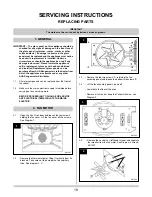
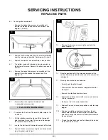
To change the top element:
• Remove the single fixing screw and carefully pull
forward the element to expose the connections. See
diagram 9, Arrow A.
6.3
• Remove the two wires and draw the element forward to
clear the two support brackets. See diagram 9, Arrow B.
6.4
• Replace the element and reassemble in reverse order.
6.5
• The bottom element is situated under a loose plate in
the bottom of the oven. Remove the plate to expose the
element.
6.6
• Remove the single fixing screw and carefully pull the
element forward to expose the connections. See
diagram 10.
6.7
• Remove the wires, replace the element and
reassemble in reverse order.
7.1
• To replace the Fan Oven Thermostat, follow steps 2.1 to
2.4 above:
7.2
• Pull the vidaflex protective sleeve off the thermostat
phial and keep for use later. Take care not to damage
the insulation behind the oven.
7.3
• Locate the fault control thermostat and pull off the knob
7.4
• Remove the four screws securing the control panel and
lower the panel onto its front
7.5
• Remove the two screws securing the control to the
panel, Diagram 12
7.6
Note the positions of all the wires and disconnect the
control. Alternatively, transfer each wire to the new control
individually.
7.7
Working from inside the controls area:
• Carefully pull the phial through.
• Take care that it has not become wrapped around the
other phial
• Remove the vidaflex protective sleeve
7.8
• Replace the defective control with a new one and secure
it to the front panel
• Make sure it is in the correct orientation
7.9
• Replace the wires in the correct positions, refer to wiring
diagram
7.10 • Replace the vidaflex protective sleeve from the old
control onto the new one, ensuring that it protects the
phial from coming into contact with other connections in
the control area
7.11 • Thread the phial back and feel for it through the hole in
the back of the Fan Oven
12
11
9
10
7. FAN OVEN THERMOSTAT
AR1559
AR2028
AR1591
AR1558
B
B
A
21
Содержание Two-Oven
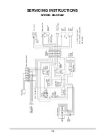
Страница 18: ...SERVICING INSTRUCTIONS WIRING DIAGRAM 18 ...

