Sealed Systems
See Fig 19.
a.
The installation must comply with the requirements of
BS 6798 and BS 449. Maximum water 82
˚
C + 3
˚
C.
b.
The safety valve set to operate 2 bar (30Ibf/In
2
) be
fitted in the flow pipe close to the boiler. There must not
be any valve between the safety valve and the boiler.
The valve should be positioned on a discharge pipe fitted
to prevent any discharge creating a hazard to occupants
or cause to damage electrical components and wiring.
c.
A pressure gauge covering at least the range 0 to 4
bar (0 to 60 Ibf/In
2
) shall be fitted in the system.
d.
A diaphragm type expansion vessel, to BS 4814, shall
be connected at a point in the return pipe close to the
boiler. The vessel must be chosen to suit the volume of
the water in the system and the charge pressure must
not be less than the static head at the point of
connection. Further details can be obtained from
“Materials and Installation Specification for Domestic
Central Heating and Hot Water” published by British Gas
and BS 7074:1.
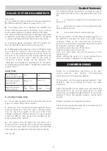
Sizing Table:
A = System Volume Litres
e.
The hot water cylinder shall be either the indirect coil
type or a cylinder fitted with a calorifer.
f.
Water lost from the system shall be replaced from a
make-up vessel and non-return valve, mounted higher
than the top of the system on the return side of the
cylinder or radiators. Where access to a make-up vessel
would be difficult make-up can be provided by pre-
pressurisation of the system.
g.
The system may be filled from the mains via a
temporary hose connection from a draw-off tap supplied
from a service pipe under mains pressure, provided that
this pressure is acceptable to the local water authority.
See Fig. 20
SEALED SYSTEM REQUIREMENTS
Air or Nitrogen
charge pressure (bar)
Pre-Pressurisation
pressure (bar)
Expansion vessel
volume (Litres)
0.5
None 1.0
Ax Ax
0.07 0.120
1.0
None 1.5
Ax Ax
0.088 0.160
The following fittings should form a permanent part of
the system and fitted in the order stated (See Figs. 19 &
20).
(i) a stop valve complying to the requirements of
BS 1010: 2.
(ii) an anti-vacuum valve of a type approved by the
National Water Council.
(iii) a non-return valve of a approved type.
h.
Fill the system until the pressure gauge registers 1.5
bar (22Ibf/In
2
). Examine for leaks and rectify where
necessary. Refer to the commissioning instructions,
switch on the boiler burner and allow the system to reach
its maximum working temperature.
Examine for leaks then turn off the boiler.
Drain the system while it is still hot.
Refill, vent and adjust the cold fill pressure to the
required value.
Whilst, refilling the system it is recommended that a
corrosion inhibitor is added to the feed water.
Follow the commissioning instructions as for open
vented systems. See Section Commissioning
Instructions with the following additions:-
Fill the system until the pressure gauge registers 1.5 bar
(22Ibf/In
2
). Clear any airlocks and check for water
soundness.
Check the operation of the safety valve, by allowing the
water pressure to rise until the valve opens. The valve
should open within
+
0.3 bar (
+
0.43 Ibf/In
2
) of the pre-set
pressure. If this is not possible conduct a manual check
and test.
Release cold water to initial filling pressure.
Any set pointer gauge should be set to coincide with the
recommended filling pressure.
COMMISSIONING
21
Содержание Heatranger 480D
Страница 8: ...Site requirements 7 DESN 510519 FIG 1...
Страница 14: ...13 Site requirements FIG 4...
Страница 23: ...Sealed Systems 22...
Страница 24: ...23...
Страница 25: ...24...

