background image

CHAPTER

5

Cab Component Installation: RS1 Installation

27

CHAPTER 5

CAB COMPONENT 

INSTALLATION

RS1 INSTALLATION

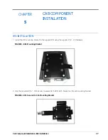
1. Install the RS1 mounting bracket to the suppled RS1 using the supplied 1/4” - 20 hardware. 

FIGURE 1.  RS1 Mounting Bracket

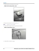
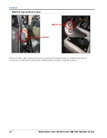
2. Use the provided 5/16” - 18 lock nuts to assemble the RS1 latch bracket on the cab mounting bracket. 

FIGURE 2.  RS1 Secured to Cab Mounting Bracket

Содержание RS1/HDU

Страница 1: ...RBR Enterprise Vector 300 LS Venturi LS RS1 HDU Installation Manual Manual No 016 5035 002 Rev A 10 18 E32227 Copyright 2018...

Страница 2: ...ven Industries shall not be held responsible for any modifications or repairs made outside our facilities nor damages resulting from inadequate maintenance of this system As with all wireless and sate...

Страница 3: ...lve 12 Mount the Steering Valve 13 Install the Left and Right Steering Hoses 14 Install the Pressure and Tank Hoses 17 Install the Load Sense Hoses 19 Hydraulic Diagram 21 Chapter 4 Wheel Angle Sensor...

Страница 4: ...Table of Contents ii RBR Enterprise Vector 300 LS Venturi LS RS1 HDU Installation Manual...

Страница 5: ...S1 HDU observe the following safety measures Be alert and aware of surroundings Do not operate RS1 HDU or any agricultural equipment while under the influence of alcohol or an illegal substance Remain...

Страница 6: ...tree limbs debris attachments Be placed in areas of or in contact with machine components which develop temperatures higher than the temperature rating of harness components Wiring should be protected...

Страница 7: ...ter sprays can penetrate seals and cause electrical components to corrode or otherwise become damaged When performing maintenance Inspect all electrical components and connections for damage or corros...

Страница 8: ...CHAPTER 1 4 RBR Enterprise Vector 300 LS Venturi LS RS1 HDU Installation Manual...

Страница 9: ...tor 300 LS Venturi LS FIGURE 1 RBR Vector 300 LS PREPARING FOR INSTALLATION Before installing the RS1 HDU system park the machine where the ground is level clean and dry Turn off the machine and leave...

Страница 10: ...Industries recommends the following best practices when installing the RS1 HDU system Use part numbers to identify the parts Do not remove the plastic wrap from a part until it is necessary for insta...

Страница 11: ...rs see us and are eager to gather ideas on how we have been helping or how we can do better To serve you best please send an email with the following information to techwriting ravenind com RBR Enterp...

Страница 12: ...CHAPTER 2 8 RBR Enterprise Vector 300 LS Venturi LS RS1 HDU Installation Manual...

Страница 13: ...2 Introduction Updates 9 INTRODUCTION...

Страница 14: ...CHAPTER 2 10 RBR Enterprise Vector 300 LS Venturi LS RS1 HDU Installation Manual...

Страница 15: ...service When disconnecting or purging hydraulic hoses be aware that the hydraulic fluid within the machine s system may be extremely hot and under high pressure Tampering with hydraulic valves may cau...

Страница 16: ...ble connections remain the same Fitting Part Number Port Fitting 6 JIC M to 10 SAE O Ring M Straight Adapter 333 0012 106 A B Fitting 6 JIC M F 90 Swivel Elbow 333 0012 042 A B Fitting 4 JIC M to 6 SA...

Страница 17: ...he valve mounting bracket using four 5 16 18 x 7 8 hex bolts P N 311 0052 104 and four 5 16 lock washers P N 313 1000 019 3 Remove the top bolt from the machine s catwalk 4 Align the lip of the valve...

Страница 18: ...ERING HOSES FIGURE 4 Steering Orbital Location 1 Locate the machine s steering orbital under the hood just in front of the cab FIGURE 5 Left Steering Port on Steering Orbital 2 Remove the cap from the...

Страница 19: ...Install the straight end of the supplied hydraulic hose P N 214 1000 780 on the open port of the tee fitting FIGURE 7 Left Steering Hose Installed on Steering Valve 4 Connect the 90 end of the install...

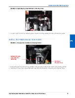
Страница 20: ...ee fitting installed in the right steering port lower right corner of the steering orbital FIGURE 9 Right Steering Hose Installed on Steering Orbital 6 Install the straight end of the supplied hydraul...

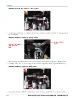
Страница 21: ...itting installed in Port B of the steering valve INSTALL THE PRESSURE AND TANK HOSES FIGURE 11 Pressure Hose Installed on Steering Orbital 1 Remove the cap from the tee fitting installed in the pressu...

Страница 22: ...ank Hose Installed on Steering Orbital 4 Remove the cap from the tee fitting installed in the pressure port upper left corner of the steering orbital 5 Install the 12 JIC end of the supplied hydraulic...

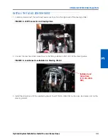
Страница 23: ...e of the steering orbital FIGURE 15 LSPV Connection on Steering Valve 2 Connect the machine s load sense hose to the fitting installed in Port LSPV of the steering valve FIGURE 16 Load Sense Hose Inst...

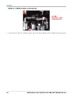
Страница 24: ...uri LS RS1 HDU Installation Manual FIGURE 17 LS STEER Connection on Steering Valve 4 Connect the 90 end of the installed hydraulic hose to the fitting installed in Port LS STEER of the steering valve...

Страница 25: ...Hydraulic System Installation Hydraulic Diagram 21 HYDRAULIC SYSTEM INSTALLATION HYDRAULIC DIAGRAM...

Страница 26: ...CHAPTER 3 22 RBR Enterprise Vector 300 LS Venturi LS RS1 HDU Installation Manual...

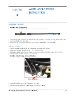
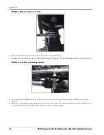
Страница 27: ...is installed later in the procedure INSTALL THE WAS 1 Park the machine on a level surface with the wheels pointing straight forward 2 Remove the nuts and clamp from the 3 x 3 8 16 U bolt clamp 3 Inst...

Страница 28: ...he rod end of the left steering cylinder so the threaded ends of the U bolt point up FIGURE 4 U Bolt on Left Steering Cylinder 8 Use the provided hardware U bolt 3 8 long spacers and 5 16 washers to i...

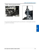
Страница 29: ...ble the WAS 25 WHEEL ANGLE SENSOR INSTALLATION FIGURE 5 WAS Rod Mounting Bracket Installation 10 Turn the machine s wheels to the left and right locks to ensure the sensor is not over compressed or ex...

Страница 30: ...CHAPTER 4 26 RBR Enterprise Vector 300 LS Venturi LS RS1 HDU Installation Manual...

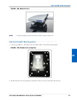
Страница 31: ...ATION RS1 INSTALLATION 1 Install the RS1 mounting bracket to the suppled RS1 using the supplied 1 4 20 hardware FIGURE 1 RS1 Mounting Bracket 2 Use the provided 5 16 18 lock nuts to assemble the RS1 l...

Страница 32: ...ing location on the cab roof FIGURE 3 RS1 Mounting Location on Roof 4 Remove the machine plate from the top of the roof NOTE The plate is no longer needed 5 Install the RS1 latch plate on the roof usi...

Страница 33: ...E It may be necessary to adjust the latch in order to secure the RS1 unit CAB COMPONENT INSTALLATION 1 Use the provided 1 4 20 flanged nuts to install the HDU on the HDU mounting plate FIGURE 6 HDU In...

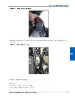
Страница 34: ...HDU Mounting Location 3 Use the provided machine hardware to mount the HDU mounting bracket on the floor with the connectors facing the seat FIGURE 8 Installed HDU INSTALL THE MASTER SWITCH 1 Use the...

Страница 35: ...r Switch in Enclosure 2 Install the master switch in a convenient location using either self tapping screws or double sided tape not provided FIGURE 10 Installed Master Switch INSTALL SYSTEM CABLES HD...

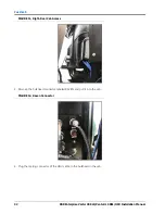
Страница 36: ...Venturi LS RS1 HDU Installation Manual FIGURE 11 Right Rear Cab Access 3 Remove the bulkhead connector labeled RAVEN and pull it into the cab FIGURE 12 Raven Connector 4 Plug the mating connector of...

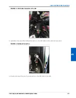
Страница 37: ...ONENT INSTALLATION FIGURE 13 HDU Cable Connection in the Cab 5 Install the other end of the bulkhead connector on the HDU cable into the machine s rear panel FIGURE 14 Bulkhead Connection 6 Route and...

Страница 38: ...e HDU Switch Cable P N 115 4010 028 2 Connect the 8 pin plug on the HDU switch cable to the receptacle on the HDU cable 3 Connect the 4pin Master connector on the HDU switch cable into the master swit...

Страница 39: ...e not used for this installation Zip tie the two cables together and place in a convenient location VALVE CABLE 1 Identify the HDU Valve cable P N 115 4010 044 2 Connect the 12 pin connector on the HD...

Страница 40: ...ector on the HDU Valve Cable 4 Route the HDU valve cable outside of the cab using the circular hole in the cab floor FIGURE 20 Feeding HDU Cable out of Cab 5 Route the HDU valve cable to the steering...

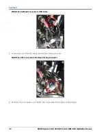
Страница 41: ...ons 7 Route and connect the WAS connector on the HDU valve cable to the WAS FIGURE 22 WAS Cable Connected to WAS RS1 CABLE 1 Identify the RS1 Cable P N 115 4010 068 2 Connect the round bulkhead connec...

Страница 42: ...ation Manual FIGURE 23 Bulkhead Connector to HDU Cable 3 Connect the end of the RS1 cable to the machine s mating connector FIGURE 24 RS1 Connected to Machine s Mating Connector 4 Route the 12 pin con...

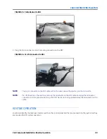
Страница 43: ...1 cable will not be used Leave the dust cap on the connector NOTE If an ISO bed is on the machine remove the terminator on the RS1 cable and plug the terminator connector into the provided dust cap If...

Страница 44: ...DU Installation Manual FIGURE 27 Resume Switch Location Refer to the Raven RS1 Guidance and Steering Calibration and Operation Manual P N 016 4010 001 for instructions on calibrating the RS1 system ad...

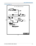
Страница 45: ...Cab Component Installation System Diagrams 41 CAB COMPONENT INSTALLATION SYSTEM DIAGRAMS...

Страница 46: ...CHAPTER 5 42 RBR Enterprise Vector 300 LS Venturi LS RS1 HDU Installation Manual...

Страница 47: ...ENDIXAKITS LISTS KITS The following kits are included in this appendix TABLE 1 RS1 HDU Kits Description Kit Number Kit WAS RBR 117 0192 053 Kit Hydraulic PVG Dynamic Load Sense 117 0199 126 Kit HDU RB...

Страница 48: ...VENT DAMAGE DURING SHIPPING FOR LABEL CONTENTS REFER TO LABEL SPEC 004 0159 001 SECTION 1 1A NOTES RAVEN INDUSTRIES INC SIOUX FALLS SD 57104 THIS KIT TO CONTAIN THE FOLLOWING ITEMS LISTED BELOW REVISI...

Страница 49: ...GED ACCORDING TO RAVEN SPEC 013 0159 016 SECTIONS A AND B TITLE CODE IDENT NO SIZE M Metric 14979 A DRAWN JJP 7 25 12 SCALE NA CAN BE SUPPLIED BY ANY MANUFACTURER VENDOR MEETING SPECIFICATIONS OUTLINE...

Страница 50: ...SCREW CSK 1 4 20 UNC x 0 50 BOLT 5 16 18 UNC x 0 88 LG BOLT HEX 3 8 16 UNC x 0 25 LG NUT FLANGED LOCK 1 4 20 UNC APPR DATE BOX SHIPPING LABELED BOX 1 OF 2 SHEET WARRANTTY HELP 016 5035 002 ECU HYDRAU...

Страница 51: ...APPENDIX A 44 RBR Enterprise Vector 300 LS Venturi LS RS1 HDU Installation Manual...

Страница 52: ...talling Fittings in the SmarTrax Valve 12 Installing Left and Right Steering Hoses 14 Installing Load Sense Hoses 19 Installing Pressure and Tank Hoses 17 I Introduction Kit Contents 7 Preparing for I...

Страница 53: ...Index 46 RBR Enterprise Vector 300 LS Venturi LS RS1 HDU Installation Manual...

Страница 54: ...r s responsibility The Return Materials Authorization RMA number must appear on the box and all documentation including proof of purchase must be included inside the box to be sent to Raven Industries...

Страница 55: ...claim and send it to Raven Industries for final approval The freight cost to Raven Industries will be the customer s responsibility The Return Materials Authorization RMA number must appear on the box...

Отзывы: