C
HAPTER
3
18
RBR Enterprise Vector 300 LS/Venturi LS RS1/HDU Installation Manual
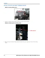
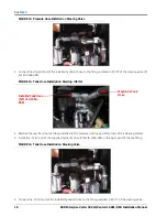
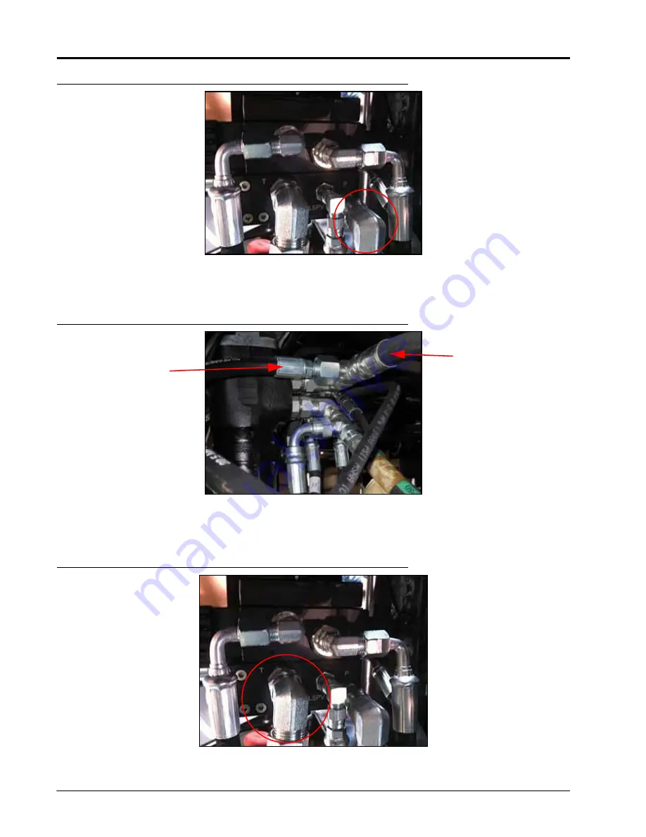
FIGURE 12. Pressure Hose Installed on Steering Valve
3. Connect the straight end of the installed hydraulic hose to the fitting installed in Port P of the steering valve (P/
N 334-0003-088).
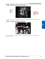
FIGURE 13. Tank Hose Installed on Steering Orbital
4. Remove the cap from the tee fitting installed in the pressure port (upper-left corner) of the steering orbital.
5. Install the -12 JIC end of the supplied hydraulic hose (P/N 214-1000-959) in the open port of the tee fitting.
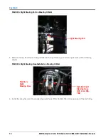
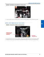
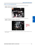
FIGURE 14. Tank Hose Installed on Steering Valve
6. Connect the -10 JIC end of the installed hydraulic hose to the fitting installed in Port T of the steering valve.
Installed Tank Hose
(P/N 214-1000-
959)
Machine’s Tank
Hose
Содержание RS1/HDU
Страница 4: ...Table of Contents ii RBR Enterprise Vector 300 LS Venturi LS RS1 HDU Installation Manual...
Страница 8: ...CHAPTER 1 4 RBR Enterprise Vector 300 LS Venturi LS RS1 HDU Installation Manual...
Страница 12: ...CHAPTER 2 8 RBR Enterprise Vector 300 LS Venturi LS RS1 HDU Installation Manual...
Страница 13: ...2 Introduction Updates 9 INTRODUCTION...
Страница 14: ...CHAPTER 2 10 RBR Enterprise Vector 300 LS Venturi LS RS1 HDU Installation Manual...
Страница 25: ...Hydraulic System Installation Hydraulic Diagram 21 HYDRAULIC SYSTEM INSTALLATION HYDRAULIC DIAGRAM...
Страница 26: ...CHAPTER 3 22 RBR Enterprise Vector 300 LS Venturi LS RS1 HDU Installation Manual...
Страница 30: ...CHAPTER 4 26 RBR Enterprise Vector 300 LS Venturi LS RS1 HDU Installation Manual...
Страница 45: ...Cab Component Installation System Diagrams 41 CAB COMPONENT INSTALLATION SYSTEM DIAGRAMS...
Страница 46: ...CHAPTER 5 42 RBR Enterprise Vector 300 LS Venturi LS RS1 HDU Installation Manual...
Страница 51: ...APPENDIX A 44 RBR Enterprise Vector 300 LS Venturi LS RS1 HDU Installation Manual...
Страница 53: ...Index 46 RBR Enterprise Vector 300 LS Venturi LS RS1 HDU Installation Manual...


