2524 ChronoCom Programming
Work Sheet for Custom Secondary-Clock Code
Bit
Value
Bit
Value
03
10
04 11
05
12
06
13
07 14
Description
Starting hour: any number between “01” and “12.” Enter "80"
to select every hour.
Starting minute: any number between ”00” and ”59.” Enter “80”
to select every minute.
Starting
second:
any number between “00” and “59.” Enter “80”
to select every second.
How long the relay should remain “on”: indicate whether your
units are seconds ("S") or minutes (“M”).*
Number of cycles.
How long the relay should remain “off’: indicate whether your
units are seconds (“S”) or minutes (“M").*
Select the output relay that this seven-byte block will control:
enter “1” for
Out 5” or Out
7";
enter “2” for Out
6 or
Out
8.**
* The way
you
enter this number during programming
will determine whether the 2524 interprets it as minutes
or seconds: after typing the number, press
Enter
for
seconds or
Funct
for minutes.
**You must coordinate three factors to direct a seven-
number block to a particular clock or motor in the clock:
You must wire the clock to a particular relay (Out 5.
Out 6,
Out 7,
or Out 8).
In Mode A, you must enter the Custom Code as
either the first correction code (the only choice
when only one code is used) or the second code. In
a singlecode system, the first correction code con-
trols
Out
7
and
Out 8; in
a two-code system, the first
code controls Out5 and
Out
6, and the second code
controls Out 7 and
Out
8.
Use the seventh number of the block to designate
the odd or even relay.
Note: Although Mode!
A and the seventh number in
the block each designate two possible relays, in com-
bination they designate only one relay. For example,
choosing the second code in Mode A limits the relay
choice to 7 or 8; entering a “2” in the seven-number
block designates Relay 6 or 8. Only
Out
8 matches both
these designations.
Example
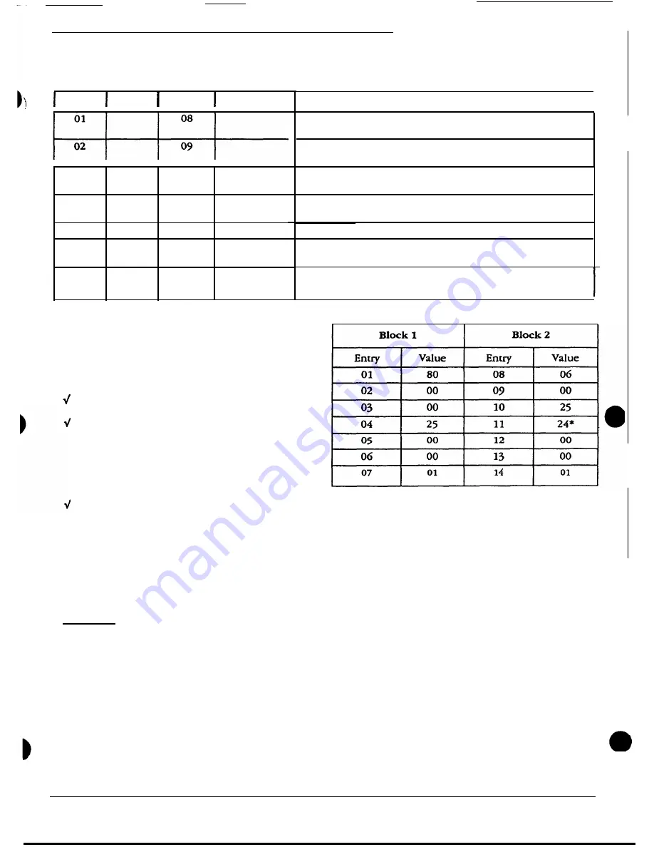
The following table shows how the correction code for
Rauland analog clocks (regular Correction Code 1) would
be set up as a special code. This is done for illustration
only; you would not usually need to enter a regular code
as a special code (the only exception would be entering a
simple standard code for each seven-number block, in
order to get two corrections in a single code and thereby
free up two output terminals).
Commentary:
Entry 1: “80” = hourly correction.
Entry 2: “00” = start the correction pulse during the
“zero” minute.
Entry 3: “00” =
start the correction pulse on the “zero”
second.
Entry 4: “25” = close the relay for 25 seconds per
pulse.
Entry
5: “00” = only one correction pulse.
Entry 6: “00”
matches Entry 5: no time between pulses,
since there is only one pulse.
Entry 7: “01 ” =
send this correction
out the odd-num-
bered relay.
Entry 8:
“06” = start the 12-hour correction during the
sixth hour.
Entry
9: “00” = start the 12-hour correction during the
“zero” minute.
Entry
10:
“25 ” =
start the correction 25 seconds after
the minute. Note that the standard code would start this
at “00” seconds. The difference here is that we are using
the same output terminal for both the hourly and the
12-hour correction (see Entries 7 and 14). Therefore, we
have to wait 25 seconds for the hourly pulse to end (Entry
4) before beginning this pulse.
Entry 11: “24” = close the relay for 24 minutes.
Entry
12: (Like Entry 5.)
Entry 13: (Like Entry 6.).
Entry 14: (Like Entry 7.)
4/90
3
Page 13


