background image

36

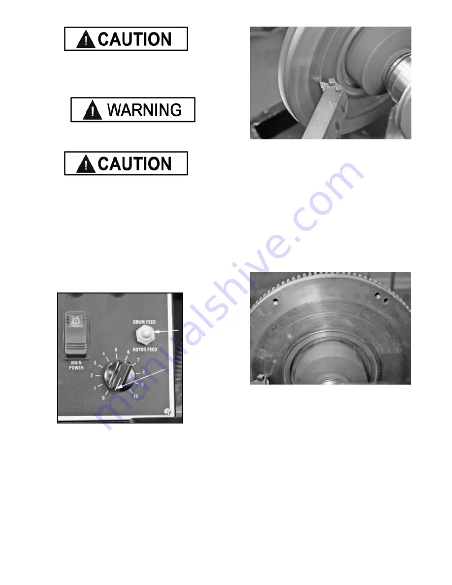
ENSURE THAT THE CUTTING TIP IS CLEAR OF THE 

FLYWHEEL PRIOR TO TURNING ON THE SPINDLE 

MOTOR.

MAKE SURE THE DRUM / ROTOR CROSS FEED 

SWITCH IS IN THE NEUTRAL POSITION.  

K

EEP HANDS clear of moving parts at all times. Keep 

hair, loose clothing, neckties, shop rags, jewelry, fingers, 

and all parts of body away from moving parts. Always 

wear safety glasses or a face shield. Cutting an exposed 

surface such as a brake drum, rotor or flywheel will pro-

duce flying chips and debris.

9..  Move the Feed Selector Switch to the Neutral 

position.

10. Set the speed feed dial to 0.

11. Turn on the Main Spindle Power Switch.

12. Rotate the Spindle Feed Hand Wheel clock wise until 

the Cutter begins to cut a shallow scratch cut in the 

flywheel.

13. Back off the Cutter by turning the Spindle Feed Hand 

Wheel Clock wise.

14. Turn off the Main Spindle Power.

15. Examine the scratch cut making sure it is uniform 

around the entire circumference of the flywheel. If the 

scratch cut appears to be deeper on one side of the fly-

wheel and not a  uniform depth, remove the flywheel from 

the arbor, check the mounting adapters and arbor for 

nicks, burrs, or chips, remount the flywheel, and repeat the 

process.


Once the flywheel is determined to be mounted properly 

and the scratch cut is good, continue on the machining 

the Flywheel in Step 18.

Содержание RL-8500

Страница 1: ...de by the purchaser against the transportation company at the time shipment is received BE SAFE Your new Ranger brake lathe was designed and built with safety in mind However your overall safety can b...

Страница 2: ...maintenance This warranty is exclusive and in lieu of all other warranties expressed or implied In no event shall Ranger Products be liable for special consequential or incidental damages for the bre...

Страница 3: ...d caution instructions may lead to serious personal injury or death to operator or bystander or damage to property Do not operate this machine until you read and understand all the dangers warnings an...

Страница 4: ...wner is to read and follow these instructions t Follow all installation instructions t Make sure installation conforms to all applicable Local State and Federal Codes Rules and Regulations such as Sta...

Страница 5: ...ned parts and into bearings causing undue wear They may also contact persons in the area causing personal injury BEFORE YOU BEGIN Receiving The shipment should be thoroughly inspected as soon as it is...

Страница 6: ...and all parts of body away from moving parts Non slip footwear is recommended t ALWAYS UNPLUG EQUIPMENT from electrical outlet when not in use Never use the cord to pull the plug from the outlet Gras...

Страница 7: ...quieter operation and reduce chatter and vibration An independent cross feed motor eliminates the need for plastic or bronze shear gears which are expensive and timely to replace A convenient top stor...

Страница 8: ...grooving and makes boots a thing of the past Massive tapered spindle bearings offer superior weight support during rotation A 450 pound cast iron body and a solid work bench eliminates transient vibr...

Страница 9: ...e area selected should be well lit easy to clean and should be away from oil grease etc Avoid areas where bystanders and customers may be present Proper unit installation is necessary for safe use and...

Страница 10: ...10...

Страница 11: ...ption 1 Upper Chip Tray 2 Cross Feed Assembly 3 Twin Cutter Head 4 Plastic Shield Guard 5 Work Light 2 6 Power Control Box 7 Upper Panel Assembly 8 Tool Tray 9 Spindle Assembly 10 Work Bench Lower Pan...

Страница 12: ...PINDLE 4 Using a shop crane or other heavy lifting device WITH NON MARRING STRAPS OR WRAPPED CHAINS CAPABLE OF SUPPORTING THE WEIGHT OF THE LATHE Raise the lathe over the bench Before lowering the Lat...

Страница 13: ...the Cutting Tips into the tool holders and the Tool Holders into the Cutting Assembly Always extend the Tool Holders the minimum required to perform the cutting operation 5 Install the Twin Cutting h...

Страница 14: ...of the lathe See page 37 Cross Feed Assembly The cross feed forward and aft draws the tool bit micro dial twin cutters or boring bar across the face of a brake rotor or flywheel when the cross feed R...

Страница 15: ...se a rag or a brush to remove metal chips shavings and dust from the lathe STEP 4 Brake Rotor Drum Inspections 1 Before attempting any resurfacing rotor and or drum inspection is necessary Determine t...

Страница 16: ...lf Aligning Spacer should always be used next to the Arbor Nut when tightening To avoid overtightening wrench turn the Arbor Nut counterclock wise until the drum and or adapters become fixed snug on t...

Страница 17: ...r an edge Various adapters and or spacers may be used to fill out the shaft of the arbor Mounting Hubbed Brake Drums Tapered centering cones or double taper adapters fit in the bearing seats Be sure t...

Страница 18: ...urfaced if scored or it has a small amount of runout provided it is within the minimum thickness requirement D After the rotor is machined measure the thickness again and if it is not within the allow...

Страница 19: ...19 Familiarize yourself with the assemblies and controls used during the Rotor Machining procedure...

Страница 20: ...lock wise until the Cutting tips are clear of the edge of the rotor you will be turning 5 Wipe any debris from the locator and arbor 6 Ensure the Rotor is free from debris 7 Mount the Rotor onto the a...

Страница 21: ...s rotor Review the cautions and dangers section and the general safety information at the beginning of this manual 10 Loosen the Cross Feed Hand Wheel Lock Knob 11 Loosen the Cross Feed Lock Knob 12 T...

Страница 22: ...the inner knurled dial indicator knobs clockwise with your right hand until ZERO is positioned at top dead center and lined up with the tick mark This will give you an initial zero set starting point...

Страница 23: ...n the Cross Feed Hand Wheel clockwise until the Cutters are just past the inside edge of the face of the rotor being careful not to run the carbide inserts into the hub portion of the rotor 6 Adjust e...

Страница 24: ...ning When the Cutter is finished 18 Set the Speed Feed Dial to 0 19 Move the Feed Selector Switch to Neutral 20 Turn off the Main Power Switch 21 Loosen the Cross Feed Hand Wheel lock 22 Back off the...

Страница 25: ...Tips will clear of the edge of rotor face 2 Loosen the Cross Feed Locking Nut 3 Loosen the Cross Feed Hand Wheel Lock Knob 4 Turn the Cross Feed Hand Wheel counter clock wise until the Cutting Tips a...

Страница 26: ...ng Nut against the Cup reverse threaded 12 Firmly tighten the Locking Nut with the Spanner Wrench reverse threaded 13 Mount the Silencer Band and double check making sure the band is centered on the r...

Страница 27: ...27 DRUM AND FLYWHEEL SET UP Familiarize yourself with the assemblies and controls used during the Drum and Flywheel Machining procedure...

Страница 28: ...cutting tip is not excessively worn Sharp cutting tips must be used at all times A dull cutter will affect the finish of both drums and rotors If the cutting edge is damaged replace it promptly Be su...

Страница 29: ...rse threaded 8 Firmly tighten the Locking Nut with the Spanner wrench reverse threaded 9 Mount the Silencer Band and double check the Silencer Band is centered on the drum and securely fastened Always...

Страница 30: ...assembly Tighten the nut firmly 4 Rotate the Spindle Feed hand Wheel counter clock wise until the Cutter is halfway across the inner face of the drum 5 Tighten the Spindle Locking Knob 6 Tighten the S...

Страница 31: ...e Speed Feed Dial to 0 16 Turn on the Main Power Switch 17 Rotate the Cross Feed Hand Wheel counter clock wise until the Cutter begins to cut a shallow scratch cut in the drum 18 Back of the Cutter by...

Страница 32: ...8 Check all clearances closely to make sure that nothing will crash when the power is turned on and the drum starts rotating NOTE It may help to manually turn the Drum by hand to check all clearances...

Страница 33: ...he machined Surface If your cutting bits are in good condition and the feed rate was set at six of below the finish should be excellent If necessary perform another pass until the finish is acceptable...

Страница 34: ...the appropriates cups and or backing plate as needed For illustration purposes the flywheel will be mounted without using the Quick Change Adapter System Remove the Quick Change Adapter System by reve...

Страница 35: ...edge of the flywheel surface The Cutter should be as close to 90 to the face of the flywheel as possible Using the Cross Feed Hand Wheel move the Cross Feed to its innermost position by turning the Ha...

Страница 36: ...al to 0 11 Turn on the Main Spindle Power Switch 12 Rotate the Spindle Feed Hand Wheel clock wise until the Cutter begins to cut a shallow scratch cut in the flywheel 13 Back off the Cutter by turning...

Страница 37: ...P IS CLEAR OF THE FLYWHEEL PRIOR TO TURNING ON THE SPINDLE MOTOR MAKE SURE THE DRUM ROTOR CROSS FEED SWITCH IS IN THE NEUTRAL POSITION KEEP HANDS clear of moving parts at all times Keep hair loose clo...

Страница 38: ...nter clockwise Check the machined Surface If your cutting bits are in good condition and the feed rate was set at six of below the finish should be excellent When the machining is complete 1 Loosen th...

Страница 39: ...urce 2 Open the Main Motor Cover 3 Loosen the Motor Mount Bolt 4 Raise the Belt Tensioner Handle Up to loosen the belt tension Flip the Belt Tensioner Handle Up to loosen the belt tension 5 Lift up on...

Страница 40: ...letion and tighten the four Socket Head Cap Screws 6 Replace the Cross Feed Motor Cover Spindle Feed Motor Belt Replacement NOTE Ensure that the lathe is free of chips and any metal shavings before pe...

Страница 41: ...nd under the Gears and Washers to prevent them from falling 9 Remove the old Belt 10 Install the new Belt Prior to Reassembly NOTE Take this time to inspect and repack the bearings with grease prior t...

Страница 42: ...to be certain that all systems are operating normally Follow detailed inspection and testing procedures for various components at regular intervals USE ONLY RANGER ORIGINAL OR AUTHORIZED SERVICE PART...

Страница 43: ...k all screws and fasteners tighten as needed ANNUALLY Change the Lubricant in the housing NOTE Ensure that the lathe is free of chips and any metal shavings before opening the Oil Fill Breather Cap 1...

Страница 44: ...44 MOTORFEED ASSEMBLY 39...

Страница 45: ...45 Motor Feed Assembly...

Страница 46: ...46 Drum Feed Assembly...

Страница 47: ...47 Drum Feed Assembly...

Страница 48: ...48...

Страница 49: ...Screw 1 17 Crossfeed Boot 1 18 Leadscrew 1 19 Woodruff Key 1 20 Friction Washer 1 21 Thrust Washer 1 22 Crossfeed 1 23 Stud 1 24 Set Screw 1 25 Brass Plug 1 26 Brass Plug 1 27 Red Knob 1 28 Brass Plu...

Страница 50: ...50 MAIN MOTOR 39 41...

Страница 51: ...in 2 16 Bearing 1 17 Race 1 18 Retaining Ring 1 19 Freeze Plug 1 20 Guide Bar 1 21 Set Screw 2 22 0 Ring 1 23 Bushing 1 24 Hex Nut 1 25 Belt 1 26 Pulley 1 27 Set Screw 2 28 Key 1 29 Main Motor 1 30 0...

Страница 52: ...52...

Страница 53: ...1 Quill 1 12 Oil Seal 1 13 Oil Seal Adapter Ring 1 14 Screw 2 15 Rear Flange 1 16 Shim 3 17 Thrust Washer 1 18 Bronze Bushing 1 19 Tool Tray 1 20 Vinyl Mat 1 21 Screw 3 22 Louver 1 23 Screw 4 24 View...

Страница 54: ...BendPak Inc Ranger Products 1645 Lemonwood Dr Santa Paula CA 93060 Tel 1 805 933 9970 Fax 1 805 933 9160 www bendpak com www rangerproducts com FOR PARTS OR SERVICE CONTACT...

Отзывы: