15
USE THESE GENERAL GUIDELINES
TO DETERMINE THE DEPTH-OF-CUT
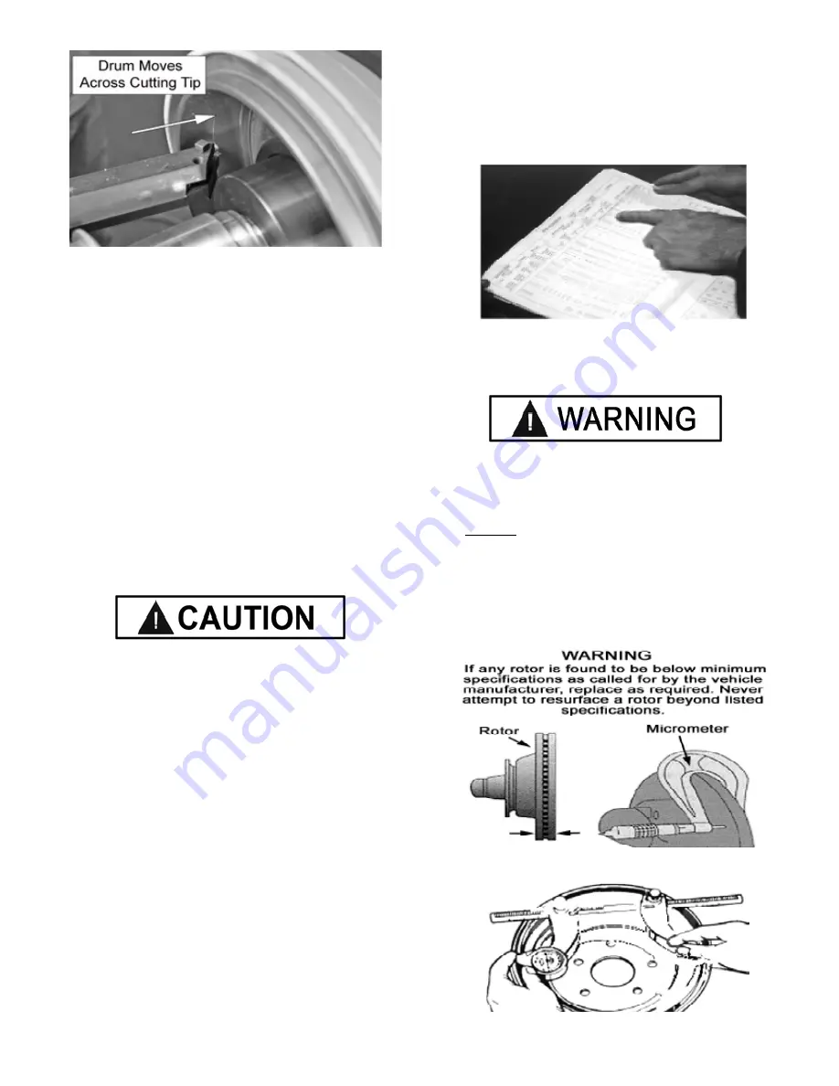
Either rough or finish cuts may be taken to resurface a
rotor. Generally, finish cuts should be 0.004” (0.10 mm)
to 0.004” (0.15 mm) per side. Very Shallow cuts of less
than 0.004” (0.10 mm) per side tend to reduce tool bit life
because the heat generated during machining isn’t
transferred to the rotor efficiently. Rough cuts may be
taken from (.006” to 0.010)
KEEP THE LATHE CLEAN OF
SHAVINGS AND CHIPS
DO NOT BLOW THE MACHINE
WITH COMPRESSED AIR!
Chips and dust may be driven between machined parts and
into bearings, causing undue wear. They may also contact
persons in the area causing personal injury.
Use a rag or a brush to remove metal chips, shavings
and dust from the lathe.
STEP 4
(Brake Rotor / Drum Inspections)
1. Before attempting any resurfacing, rotor and/or drum
inspection is necessary. Determine the manufacturer’s
specifications from an approved specification guide.
2. Using a digital micrometer or other measuring tool, record
the thickness of the rotor or drum. Observe any deep scores
and gouges. This depth will also need to be recorded.
IF ANY ROTOR IS FOUND TO BE BELOW MINIMUM
SPECIFICATIONS AS CALLED FOR BY THE VEHICLE
MANUFACTURER, REPLACE AS REQUIRED.
NEVER ATTEMPT TO RESURFACE A ROTOR
BEYOND LISTED SPECIFICATIONS
3. Determine if the total amount of material to be removed
will meet the manufacturer’s minimum specifications. If
any rotor is found to be below minimum specifications as
called for by the vehicle manufacture, replace as required.
Содержание RL-8500
Страница 10: ...10...
Страница 19: ...19 Familiarize yourself with the assemblies and controls used during the Rotor Machining procedure...
Страница 44: ...44 MOTORFEED ASSEMBLY 39...
Страница 45: ...45 Motor Feed Assembly...
Страница 46: ...46 Drum Feed Assembly...
Страница 47: ...47 Drum Feed Assembly...
Страница 48: ...48...
Страница 50: ...50 MAIN MOTOR 39 41...
Страница 52: ...52...


