Serial Bus Analysis
R&S
®
RTC1000
142
User Manual 1335.7352.02 ─ 02
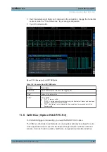
At the physical level, CAN is a differential signal, therefore a differential probe is rec-
ommended for decoding. Nevertheless, standard probes are also suitable to capture
the signals. The standard data rates range between 10 kBit/s and 1 MBit/s.
A CAN message primarily consists of a start bit, the frame ID (11 bit or 29 bit), the data
length code DLC, the data, a CRC, acknowledge bit, and an end bit.
11.6.1 CAN Bus Configuration
Before you configure the bus, set the correct logic level (threshold).
●
●
"To set the threshold for logic states"
on page 108. The
default value is 500
mV.
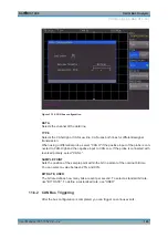
To select the CAN bus
1. Press the BUS key in the Vertical section.
2. In the short menu, select the bus: "B1" or "B2".
3. In the "BUS" menu, press the "BUS TYPE" softkey.
4. Use the UNIVERSAL knob to select "CAN":
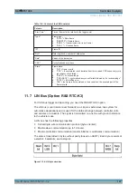
To configure the CAN bus
1. In the "BUS" menu, press "CONFIGURATION".
2. Configure the bus. The settings are described below.
CAN Bus (Option R&S
RTC-K3)
Содержание RTC1000
Страница 1: ...R S RTC1000 Digital Oscilloscope User Manual User Manual 1335 7352 02 02 S 2...
Страница 57: ...Trigger R S RTC1000 57 User Manual 1335 7352 02 02 Figure 5 3 External trigger signal External Trigger Input...
Страница 225: ...Remote Commands Reference R S RTC1000 225 User Manual 1335 7352 02 02 Suffix m 1 6 Selects the measurement Measurements...


