Page 54
45349C
© 2001 Radionics
D6412 Installation Guide
13.3.4 Press [4] for Test Report
When you press the [4] key, the panel will attempt to send a Test report. If there is a system trouble present at the
time of the test, the panel sends a Test, Off Normal report
The test report follows the routing for the Automatic Test report.
If the test communication is unsuccessful, the panel creates a system trouble and a communication failure.
IMPORTANT
This test report is the only report sent when the Installer Switch is closed.
13.3.5 Press [5] for Point Status
Pressing [5] displays the sensor loop status for the first location in the system. The location, area, point number,
and electrical status (open, short, or normal) are shown. See
Locations
in the
D6412 Program Entry Guide
(P/N:
45351) for a complete description of the relationship between locations, areas, and points.
Pressing the [*] key advances the display to the status for the next point.
Pressing the [Cmd] key exits the Point Status mode.
13.3.6 Press [6] for Output Test
When you press [6] for Output test, the display shows
Output 1, Hold [*] to test
. Holding [*] activates
Output 1 for as long as you hold [*] down. When you release the [*] key, the display advances to the next output.
Pressing the [*] key (without holding) advances to the next output, without activating the output displayed.
13.3.7 Press [7] for RF Menu
Pressing [7] moves the system into the RF Menu. This menu consists of three scrolling choices that allow you to
add RF ID codes, test RF devices and view or remove RF ID codes.
13.3.7.1 Adding RF ID Codes
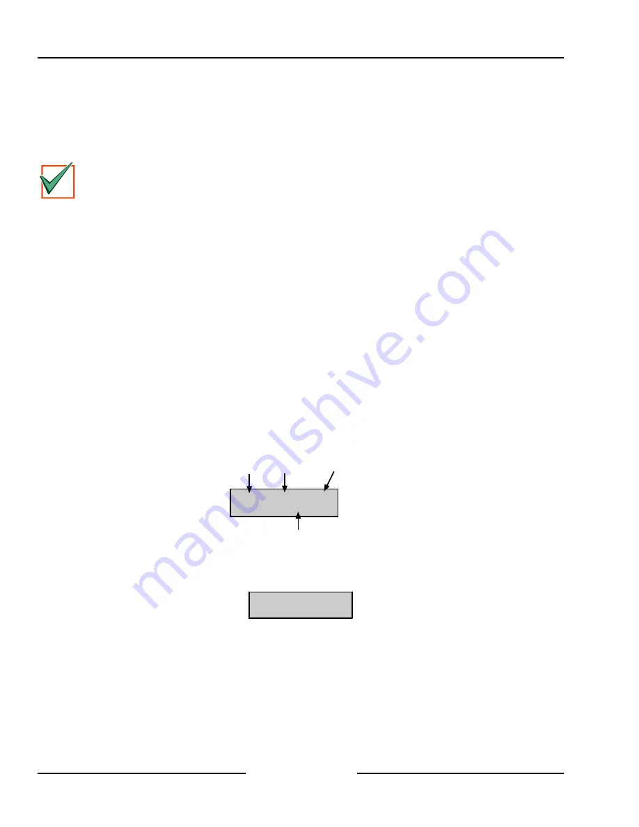
To add RF ID codes into the system, press [1] when “Add RF ID? Press 1.” scrolls across the display. The display
will then show the following:
Loc9
A1
Pt9
To add push 9*.
Location Area
Point
Number
Key sequence to press
Figure 42: Adding RF ID Codes Menu Display
To add the location shown in Figure 42 as an RF device to the system (Location 9 used as an example), press [9]
followed by [*]. The following display will then be shown:
Enter ID for
Loc9
A1
Pt9.
Figure 43: RF ID Code Display
Enter the 9-digit ID code found on the back of the RF device and then press [Cmd]. “ID added. Press #.” will appear
on the second line of the display, indicating that the code has been successfully entered and accepted. Press
[Cmd].
If an error message appears instead of “#,” make sure you enter the code as printed on the back of the device and
that you only enter nine digits.
Press [Cmd]. The display returns to the first location designated as an RF device and scrolls through other RF
device locations (if any). You may enter the desired location number and add the ID code as described above.
D6412
Installer’s Keypad & Installer Mode


