background image

Installation Manual 


COMBI  -  TA01A011.B1003 


5

FLUE POSITION 


IMPORTANT:  THE FLUE SYSTEM SHALL BE INSTALLED IN ACCORDANCE WITH THE RECOMMENDATIONS CONTAINED IN BS 
5440:1. 

The boiler MUST  be installed so that the terminal is exposed to the external air. 

It is important that the position of the terminal allows free passage of air across it at all times. 

If the terminal discharges into a pathway or passageway check that combustion products will not cause nuisance and that the terminal will 
not obstruct the passageway. 

In certain weather conditions a terminal may emit a plume of steam.  Positions where this would cause a nuisance should be avoided. 

IMPORTANT REQUIREMENT:  The correct dimensional relationship between the terminal and any obstruction, openable window or 

ventilator as shown in Fig 1 pag.7 It is ESSENTIAL TO ENSURE,  in practice, that products of combustion discharging from the terminal 
cannot re-enter the building, or any other adjacent building, through ventilators, windows, doors, other sources of natural air infiltration, or 

forced ventilation/air conditioning systems.  If this should occur, the appliance MUST BE TURNED OFF IMMEDIATELY and the local gas 

region consulted. 

Where the lowest part of the terminal is fitted less than 2m (6.6ft) above a balcony, above ground, or above a flat roof to which people have 

access, the terminal MUST be protected by a purpose designed guard.  
Where the terminal is fitted within 850mm (34in) of a plastic or painted gutter, or 450mm (18in) of painted eaves, an aluminium shield of at 

least 1000 mm (40in)  long should be fitted to the underside of the gutter painted surface. 

The air inlet/products outlet duct and the terminal of the boiler MUST NOT be closer than 25mm (1in) to combustible material.


TERMINAL POSITION 


J

E

A

G

M

F

F

A

D

H,I

TOP VIEW REAR FLUE

D

G

L

K

G

N

B.C

TERMINAL 
ASSEMBLY

PROPERTY BOUNDARY LINE

300 min


A

  Directly below an openable window, air vent or any other ventilation opening. 

300 mm 

B

  Below gutter, drain pipes or soil pipes. 

25  mm  

C

  Below eaves. 

25  mm  

D

  Below balcony or carport roof. 

25  mm  

E

  From vertical drain pipes or soil pipes. 

25  mm  

F

  From internal or external corners. 

25  mm  

G

  Above adjacent ground, roof or balcony level. 

300  mm  

H

  From a surface facing the terminal. 

600  mm  

I


Facing the terminals. 

1200  mm  

J

  From opening (door, window)in the carport into dwelling. 

1200  mm  

K

  Vertically from a terminal on the same wall 

1500  mm  

L

  Horizontally from a terminal on the same wall 

300  mm  

M

  Above an opening, air brick, opening window etc. 

300  mm 

N

  Horizontally to an opening, air brick, opening window etc. 

300  mm 


Fig. 1 

Содержание RSF 30

Страница 1: ...A01A011 B1003 Technical Specification RADIANT BRUCIATORI S p A Montelabbate PU ITALY ENGLISH INSTALLATION AND MAINTENANCE MANUAL FOR GAS FIRED WALL HUNG BOILERS Model RSF 30 E TYPE C ROOM SEALED SEDBU...

Страница 2: ......
Страница 3: ...EM page 3 GENERAL INSTALLATION REQUIREMENTS page 4 BOILER INSTALLATION page 6 ELECTRICAL CONNECTIONS page 8 13 BOILER CONTROL PANEL page 9 STARTING UP THE BOILER FOR THE FIRST TIME page 9 MULTIGAS OPE...

Страница 4: ...ion vessel 2 WARNINGS REGARDING INSTALLATION Warranty expires 12 months from date of installation and in all cases no later than 18 months from date of construction First start up must be performed by...

Страница 5: ...TU h 57774 Heating temperature adjustment C 30 80 Max working pressure heating bar 3 Min working pressure heating bar 0 3 Expansion vessel capacity initial pressure 1 bar Litres 10 Hot water flow rate...

Страница 6: ...USE ORIGINAL RADIANT APPROVED FLUE KIT SYSTEMS FLUE ACCESSORIES AND FLUE DIAPHRAGMS ONLY APPROVED RADIANT FLUE DIAPHRAGMS AND ADJUSTMENT TABLES ARE SUPPLIED WITH RADIANT ORIGINAL FLUE KIT SYSTEMS R C...

Страница 7: ...ework that supplies the boiler must be a 22 mm ininterrupted supply from meter to the isolation cock of the boiler The complete installation must be tested for soundness as described in the above code...

Страница 8: ...re the lowest part of the terminal is fitted less than 2m 6 6ft above a balcony above ground or above a flat roof to which people have access the terminal MUST be protected by a purpose designed guard...

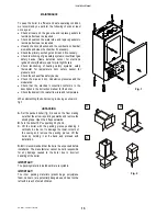
Страница 9: ...lation the boiler is equipped with a fittings kit see fig 3 IMPORTANT Before connecting the heating system pipes carefully clean the system to prevent residual dirt from entering into circulation and...

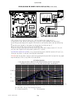
Страница 10: ...with an Anti Freeze system which comes into operation when the temperature falls to 5 C Heating sensor and 4 C Hot water sensor and protects the boiler down to 10 C external temperature To protect the...

Страница 11: ...strument panel as follows A Turn off the electrical power supply at the mains B Remove the boiler front casing C Undo the two screws on the panel and turn it to the position shown in fig 1 pos 1 D Aft...

Страница 12: ...utral and earth connections have been properly connected make sure the type of gas being supplied is the same as the type for which the boiler has been tested and approved see plate data make sure the...

Страница 13: ...N position and try the ignition procedure once again If the boiler does not start reset boiler and Set the ON OFF switch 1 to OFF and then ON position IMPORTANT should the boiler fail to ignite wait 3...

Страница 14: ...ed d calibrate the new max and min settings for the modulator e replace the gas setting plate that indicates the type of gas and nominal pressure for the boiler When converting the boiler to work with...

Страница 15: ...Y THERMOSTAT 9 ELECTRONIC GAS VALVE VK4105 10 ELECTRONIC IGNITION BOARD 11 EXPANSION VESSEL 12 3 SPEED CIRCULATION PUMP WITH AIR VENT 13 AUTOMATIC AIR VENT 14 HEATING CIRCUIT 3 bar PRESSURE RELIEF VAL...

Страница 16: ...C M1 1 2 3 4 brown light blue IG black black 17 1 PWM 12 light blue 10 11 grey black RS light blue brown 13 14 16 15 L 12 11 9 10 8 7 6 5 4 3 2 N 56 1bar PAC brown black M3 55 brown brown light blue b...

Страница 17: ...tion can be made to either the remote control fig 5 or to the terminal block fig 3 dotted line on the terminals marked SE SE WARNING The remote control connection cable must pass through a channel whi...

Страница 18: ...odulation Check that the electrical connection conforms to the description in the instruction manual for the boiler Check the domestic hot water flow rate and temperature When dismantling the boiler c...

Страница 19: ...230V ES 30 108 G 00 0416 9 43157LP SEALING CLIPS KIT FOR MULTIPLEX GROUP 9 58009LP MAIN HEAT EXCHANGER mod 30 000 kCal h 9 59012LP AIR PRESSURE SWITCH CE C6065FH1748B 9 59015LA WATER PRESSURE SWITCH...

Страница 20: ...LET HAVE BEEN CAREFULLY PREPARED BUT WE RESERVE THE RIGHT TO MAKE CHANGES AND IMPROVEMENTS IN OUR PRODUCTS WHITCH MAY AFFECT THE ACCURANCY OF THE INFORMATION CONTAINED IN THIS LEAFLET E OE ALL RIGHTS...

Отзывы: