background image

Installation Manual 


COMBI  -  TA01A011.B1003 


6

400 m

m

A

A

400 m

m

MINIMUM DISTANCE mm.

SECTION A-A

1200 min.

Balcony

MINIMUM DISTANCE mm.

45

0

60

450

60

MINIMUM DISTANCES FOR 

FIXING TO WALL 

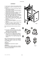
To allow access in the boiler for 

maintenance operations, the 

minimum distances shown below 

must be respected (fig. 1): 
To facilitate installation, the boiler 

is supplied with a template for 

advance location of connections to 

pipes. In this way, you may simply 
hook up the boiler when wall work 

is completed (fig.2). 


Installation Instruction   

a)


with a spirit level, draw a line 

on the wall on which the boiler 
will be installed (fig. 1);  

b)


position the top of the template 

on the line drawn with the spirit 

level (respecting the distances 
– see fig. 1) than mark the 

three points for insertion of the 

3 screw anchors or wall 

anchors for fixing the boiler 
hanging bracket (choose 

proper anchors according to 

the wall type); 

c)


fix the hanging bracket  

d)


make connections to the hot 

and cold water supply, to the 

gas pipe and to the heating 

system with the fittings. 
Connect pipes and valves as 

shown in the picture; 

e)


position the boiler paying 

attention to hang it to the 
hanging bracket and make 

final connections; 


WATER CONNECTIONS  

To facilitate installation, the boiler is equipped with a fittings kit (see fig. 3). 
IMPORTANT: 

Before connecting the heating system pipes, carefully clean the system to 

prevent residual dirt from entering into circulation and negatively affecting 
boiler function. Install a funnel with discharge under the safety valve 

(calibrated to 3 bar) to collect water in case of leaking due to overpressure. No 

safety valve is needed for the domestic water circuit, but be sure that pressure 

does not exceed 6 bar. 


avoid using pipelines of reduced diameter; 


avoid the use of tight bends and adapters in important sections; 


clean out the system thoroughly before connecting up the boiler in order to 

eliminate any residue left in the pipes and radiators; 

N.B.:


Make sure that the water and heating pipes are not used as earth 

connections for electrical apparatus.


WARNINGS  

Boilers can be installed externally, in a partially protected place (balcony – see 
fig. 4) in conformity with local Building Regulation and if the outside minimum 

temperature is not lower than –10°C. The manufacturer is not responsible for 

external installations where the outside temperature is lower than – 10°C or not in conformity with above instructions.   

Fig. 2 

87

344

286

75

5

R

55.5

53

82

80

0

102

C

F

80

70

G

M

55.5

  WITH BRACKET MOD. 1

MOD. 1

MOD. 2

  CON STAFFA MOD. 1

KIT H

MOD. 2

MOD. 1

KIT A

82

53

Fig. 1 

Fig. 3 

Fig. 4 

FIXING KIT 

R

  HEATING RETURN ¾”

G

 GAS ½” 

C

 HOT WATER ½” 

F

 COLD WATER ½” 

A

 HEATING FLOW ¾”

Содержание RSF 30

Страница 1: ...A01A011 B1003 Technical Specification RADIANT BRUCIATORI S p A Montelabbate PU ITALY ENGLISH INSTALLATION AND MAINTENANCE MANUAL FOR GAS FIRED WALL HUNG BOILERS Model RSF 30 E TYPE C ROOM SEALED SEDBU...

Страница 2: ......
Страница 3: ...EM page 3 GENERAL INSTALLATION REQUIREMENTS page 4 BOILER INSTALLATION page 6 ELECTRICAL CONNECTIONS page 8 13 BOILER CONTROL PANEL page 9 STARTING UP THE BOILER FOR THE FIRST TIME page 9 MULTIGAS OPE...

Страница 4: ...ion vessel 2 WARNINGS REGARDING INSTALLATION Warranty expires 12 months from date of installation and in all cases no later than 18 months from date of construction First start up must be performed by...

Страница 5: ...TU h 57774 Heating temperature adjustment C 30 80 Max working pressure heating bar 3 Min working pressure heating bar 0 3 Expansion vessel capacity initial pressure 1 bar Litres 10 Hot water flow rate...

Страница 6: ...USE ORIGINAL RADIANT APPROVED FLUE KIT SYSTEMS FLUE ACCESSORIES AND FLUE DIAPHRAGMS ONLY APPROVED RADIANT FLUE DIAPHRAGMS AND ADJUSTMENT TABLES ARE SUPPLIED WITH RADIANT ORIGINAL FLUE KIT SYSTEMS R C...

Страница 7: ...ework that supplies the boiler must be a 22 mm ininterrupted supply from meter to the isolation cock of the boiler The complete installation must be tested for soundness as described in the above code...

Страница 8: ...re the lowest part of the terminal is fitted less than 2m 6 6ft above a balcony above ground or above a flat roof to which people have access the terminal MUST be protected by a purpose designed guard...

Страница 9: ...lation the boiler is equipped with a fittings kit see fig 3 IMPORTANT Before connecting the heating system pipes carefully clean the system to prevent residual dirt from entering into circulation and...

Страница 10: ...with an Anti Freeze system which comes into operation when the temperature falls to 5 C Heating sensor and 4 C Hot water sensor and protects the boiler down to 10 C external temperature To protect the...

Страница 11: ...strument panel as follows A Turn off the electrical power supply at the mains B Remove the boiler front casing C Undo the two screws on the panel and turn it to the position shown in fig 1 pos 1 D Aft...

Страница 12: ...utral and earth connections have been properly connected make sure the type of gas being supplied is the same as the type for which the boiler has been tested and approved see plate data make sure the...

Страница 13: ...N position and try the ignition procedure once again If the boiler does not start reset boiler and Set the ON OFF switch 1 to OFF and then ON position IMPORTANT should the boiler fail to ignite wait 3...

Страница 14: ...ed d calibrate the new max and min settings for the modulator e replace the gas setting plate that indicates the type of gas and nominal pressure for the boiler When converting the boiler to work with...

Страница 15: ...Y THERMOSTAT 9 ELECTRONIC GAS VALVE VK4105 10 ELECTRONIC IGNITION BOARD 11 EXPANSION VESSEL 12 3 SPEED CIRCULATION PUMP WITH AIR VENT 13 AUTOMATIC AIR VENT 14 HEATING CIRCUIT 3 bar PRESSURE RELIEF VAL...

Страница 16: ...C M1 1 2 3 4 brown light blue IG black black 17 1 PWM 12 light blue 10 11 grey black RS light blue brown 13 14 16 15 L 12 11 9 10 8 7 6 5 4 3 2 N 56 1bar PAC brown black M3 55 brown brown light blue b...

Страница 17: ...tion can be made to either the remote control fig 5 or to the terminal block fig 3 dotted line on the terminals marked SE SE WARNING The remote control connection cable must pass through a channel whi...

Страница 18: ...odulation Check that the electrical connection conforms to the description in the instruction manual for the boiler Check the domestic hot water flow rate and temperature When dismantling the boiler c...

Страница 19: ...230V ES 30 108 G 00 0416 9 43157LP SEALING CLIPS KIT FOR MULTIPLEX GROUP 9 58009LP MAIN HEAT EXCHANGER mod 30 000 kCal h 9 59012LP AIR PRESSURE SWITCH CE C6065FH1748B 9 59015LA WATER PRESSURE SWITCH...

Страница 20: ...LET HAVE BEEN CAREFULLY PREPARED BUT WE RESERVE THE RIGHT TO MAKE CHANGES AND IMPROVEMENTS IN OUR PRODUCTS WHITCH MAY AFFECT THE ACCURANCY OF THE INFORMATION CONTAINED IN THIS LEAFLET E OE ALL RIGHTS...

Отзывы: