background image

INSTALLATION INSTRUCTIONS 


19

3.9  Electrical connections 


General warnings 

  The connection to the mains power supply must be carried out by professionally qualified personnel, 

registered in accordance with current legislation

.


  Always check to make sure that the appliance has an efficient earth system. This requirement is only 

satisfied if it has been properly connected to an efficient earth system installed in accordance with the 
requirements of current safety standards
 and carried out by professionally qualified personnel. 


In GB this is I.E.E. Wiring Regulation. 

This basic safety measure must be checked, verified and carried out by professionally qualified personnel.  
In case of doubt, have the electrical system checked by a qualified electrician. The manufacturer will not be 
held liable for any damage or injury caused as a result of an inefficient or inexistent earth system; 

  The boiler functions with an alternating current of 230 V and 50 Hz and has maximum power absorption of 180 

W. The appliance should be protected by a 3 A fuse. The connection to the mains electricity supply must be 
via  a  single-pole  switch,  with  at  least  3  millimetres  gap  between  open  contacts,  mounted  upstream  of  the 
appliance. Make sure that the positions of the live and neutral wires correspond to the wiring diagram; 

  Ensure  the  domestic  power  supply  is  checked  by  a  qualified  electrician  to  ensure  that  it  can  support  the 

maximum power absorption of the appliance, as indicated on the rating plate. In particular, make sure that the 
cable sizes are adequate for the power absorbed by the appliance; 

  The power  supply cable must not be replaced  by the  user. if the cable is damaged in any  way,  switch off the 

appliance and have the cable replaced by a suitably qualified electrician; 

  When  replacing  the  power  supply  cable,  only  use  cables  of  the  same  characteristics  (HO5  VV-F  3x1)  with 

maximum external Ø 8 mm; 

When using an electrical appliance, a few fundamental rules must be observed: 


Do not touch the appliance with damp or wet parts of the body or when barefoot. 


Do not pull on the electric wires. 


Do  not  leave  the  appliance  exposed  to  atmospheric  elements  (rain,  sun,  etc,)  unless  these  conditions  have 
been expressly provided for. 


Do not allow the appliance to be used by children or anyone unfamiliar with its operation; 


Содержание RKR 24

Страница 1: ...694 RKR 24_28_34 RAD ING MAN INST 1104A DIGITECH 2 REGNO UNITO EXTRAHEAT CBD Technical specification RADIANT BRUCIATORI S p A Montelabbate PU ITALY ENGLISH Instruction Manual for model RKR 24 RKR 28 R...

Страница 2: ......

Страница 3: ...17 3 8 Gas connection 18 3 9 Electrical connections 19 3 10Flue connections 21 4 Commissioning the appliance authorised personnel 4 1 General warnings 27 4 2 Filling the system 28 4 3 Filling the con...

Страница 4: ...ust be kept in a safe place and made available for future reference This Manual must be left along with the Benchmark commissioning booklet with the boiler as Regulation 29 of the HSC Gas safety insta...

Страница 5: ...ordance with the requirements of current safety standards This fundamental safety requirement must be checked and verified In case of doubt have the electrical system checked by a qualified electricia...

Страница 6: ...l unit that is easy to install and simple to operate In its simplicity the wall mounted appliance is equipped with all the appropriate accessories required to make it a fully independent boiler capabl...

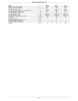
Страница 7: ...W flow rate at T 30K litr mn 11 1 13 4 16 D H W flow rate at T 35K litr mn 9 5 11 5 13 7 D H W flow rate at T 40K litr mn 8 3 10 1 12 D H W flow rate at T 50K litr mn 6 7 8 1 9 6 Dimensions Boiler cas...

Страница 8: ...temperature 50 30 C Pn C 50 8 53 51 7 Flue gas temperature 80 60 C Pn C 71 65 73 3 Flue Mass 50 30 C Pn Pr Kg h 29 95 6 65 42 50 15 30 58 95 17 34 Flue Mass 80 60 C Pn Pr Kg h 28 32 6 49 39 32 15 08 5...

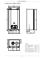
Страница 9: ...63 285 131 S R HF CWI G HR HWO 65 280 65 730 15 25 730 70 49 78 80 102 31 410 285 2 2 Dimensions RKR 24 RKR 28 LEGEND HR HEATING RETURN mm 22 HF HEATING FLOW mm 22 G GAS mm 15 CWI COLD WATER INLET mm...

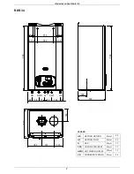
Страница 10: ...10 132 730 HF CWI G HR HWO 70 49 78 80 102 31 310 730 111 5 187 111 5 48 5 313 48 5 105 RKR 34 LEGEND HR HEATING RETURN mm 22 HF HEATING FLOW mm 22 G GAS mm 15 CWI COLD WATER INLET mm 15 HWO HOT WATER...

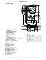
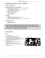
Страница 11: ...ELECTRODE 6 FAN 7 VENTURI 8 IGNITION TRANSFORMER 9 ELECTRONIC GAS VALVE 10 3 BAR PRESSURE RELIEF VALVE HTG CIRCUIT 11 AUTOMATIC AIR VENT VALVE 12 HEATING SAFETY THERMOSTAT 13 HEATING SENSOR 14 PUMP WI...

Страница 12: ...14 PUMP WITH AIR VENT 15 WATER PRESSURE GAUGE 16 FLUE HOOD 17 SAFETY THERMO FUSE 18 EXPANSION VESSEL 19 D H W SENSOR 20 CONDENSATE TRAP 21 WATER PRESSURE SWITCH 22 AUTOMATIC BY PASS 23 CONDENSATE DRA...

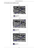
Страница 13: ...d speed Pump head at maximum speed III Flow l h Head kPa RKR 24 III II I Flow l h III Pump head at maximum speed Pump head at second speed II I Pump head at minimum speed Appliance Loss Head kPa RKR 2...

Страница 14: ...mperature display When the boiler is switched off at the switch on the control panel the word OFF appears on the display The D H W and central heating frost protection system nevertheless remain enabl...

Страница 15: ...d and 3 rd family gases BS 5449 Forced circulation hot water systems BS 6700 Installation of cold water supplies for domestic purposes 1st 2nd and 3 rd family gases BS 6798 Installation of gas fired h...

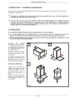
Страница 16: ...are fully recyclable It is recommended that the packing material is only removed prior to installing the boiler The manufacturer will not be held responsible for damage caused by incorrect storage of...

Страница 17: ...arances indicated in figure 1 are respected To make the installation easier the boiler is supplied with a template to enable the pipe connections to be positioned prior to fixing the appliance to the...

Страница 18: ...ains water supply and the presence of residual solids or impurities which are often present in the case of a new installation If the characteristics of the mains water supply are such that require it...

Страница 19: ...an automatic by pass is preferred Radiator valve Filling point DHW outlet Pressure reducing valve supplied Mains water inlet Static head of system Make up vessel Heating by pass if required Lockshield...

Страница 20: ...insulated to protect against frost It is also recommended that the pipe diameter is increased to 32mm 8 If the boiler is fitted in an unheated location the entire condensate discharge pipe should be...

Страница 21: ...must be a minimum of a 22 mm diameter pipe with an uninterrupted supply from meter to boiler and comply with current standards and regulations Check the internal and external seals of the gas supply s...

Страница 22: ...nection to the mains electricity supply must be via a single pole switch with at least 3 millimetres gap between open contacts mounted upstream of the appliance Make sure that the positions of the liv...

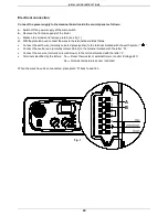
Страница 23: ...erminal board B as follows Connect the earth wire normally coloured green yellow to the terminal marked with the earth symbol Connect the neutral wire normally coloured blue to the terminal marked wit...

Страница 24: ...minal is fitted less than 2m 6 6ft above a balcony above ground or above a flat roof to which people have access the terminal MUST be protected by a purpose designed guard Where the terminal is fitted...

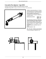
Страница 25: ...directly to the outside or can be connected to a suitable plume management system MAXIMUM FLUE LENGTH RKR 24 6 m RKR 28 6 m RKR 34 3 m The maximum flue length linear equivalent is obtained by totallin...

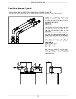
Страница 26: ...ted directly to the outside or can be connected to a suitable plume management system MAXIMUM FLUE LENGTH RKR 24 12 m RKR 28 10 m RKR 34 8 m The maximum flue length linear equivalent is obtained by to...

Страница 27: ...two separate 80 ducts MAXIMUM FLUE LENGTH 80 80 50 m 60 60 30 m The maximum flue length linear equivalent is obtained by totalling the length of linear pipe and the equivalent lengths of each bend fi...

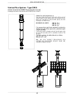
Страница 28: ...tion air while the 80 plastic inner duct discharges the exhaust fumes MAXIMUM FLUE LENGTH RKR 24 12 m RKR 28 10 m RKR 34 8 m The maximum flue length linear equivalent is obtained by totalling the leng...

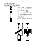
Страница 29: ...scharges the exhaust fumes MAXIMUM FLUE LENGTH RKR 24 6 m RKR 28 6 m RKR 34 3 m The maximum flue length linear equivalent is obtained by totalling the length of linear pipe and the equivalent lengths...

Страница 30: ...nd earth wires are connected properly Also make sure that the earth connection is sound Check the seals on the gas supply pipe from the mains and make sure that the meter does not register any flow of...

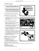
Страница 31: ...or the air evacuation process When water starts to flow out of the radiators close the air vents Use the pressure gauge M see fig 2 to check that the system pressure reaches 1 bar and that the code H2...

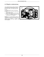
Страница 32: ...illing operation is carried out as follows see fig 1 Remove plug T and fill the trap S three quarters full with water Replace plug T and connect the drainpipe P into a condensate discharge trap confor...

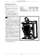
Страница 33: ...tempting to light the boiler To reset the boiler Switch off switch 1 see 2 7 Control Panel and switch it back on again and repeat the lighting procedure With the boiler ignited if the system still emi...

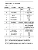
Страница 34: ...40 C P04 Heating output rising time 00 01 default 02 03 04 00 0sec 01 50 sec 02 100 sec 03 200 sec 04 400 sec P05 Water hammer prevention function 00 01 00 Off 01 On P06 D H W priority function 00 01...

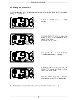
Страница 35: ...eping buttons and pressed Wait for P 00 to appear on the display 3 Release buttons and 4 Keep button S pressed and use button to select the parameter to modify 5 Release button S then re press and rel...

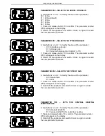
Страница 36: ...will appear on the display 8 Switch off the appliance and switch it back on again to render the new parameter operative PARAMETER P02 SELECTS THE TYPE OF GAS 6 Use buttons and to modify the value of t...

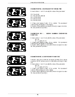
Страница 37: ...the parameter 00 off 01 on default 2 7 Press and release button S to confirm The parameter number P05 will appear on the display 8 Switch off the appliance and switch it back on again to render the ne...

Страница 38: ...parameter within the prescribed limits 00 0 x 5 0 90 90 x 5 450 7 5 min The default value is 36 180 3 min 7 Press and release button S to confirm The parameter number P08 will appear on the display 8...

Страница 39: ...the appliance and switch it back on again to render the new parameter operative PARAMETER P12 MINIMUM FAN SPEED SETTING CENTRAL HEATING 6 Use buttons and to modify the value of the parameter between...

Страница 40: ...back on again to render the new parameter operative PARAMETER P16 TELEPHONE CONTROL ACTIVATION 6 If a telephone interface is installed enable the board by setting parameter P16 at 01 7 Press and rele...

Страница 41: ...e di alimentazione mbar 20 30 37 Consumi 15 C 1013 mbar m 3 h 1 90 Consumi 15 C 1013 mbar kg h 1 42 1 4 Heating Power kW Fan frequency Hz diagram G 31 G 30 G20 CO2 Values Gas type CO2 Natural gas G20...

Страница 42: ...Pressione nominale di alimentazione mbar 20 30 37 Consumi 15 C 1013 mbar m3 h 2 65 Consumi 15 C 1013 mbar kg h 1 97 1 94 Heating Power kW Fan frequency Hz diagram G20 G30 G31 CO2 Values Gas type CO2...

Страница 43: ...as G 31 10 3 Table no 2 Frequency Gas type Minimum Hz Maximum Hz Natural gas G20 55 164 Liquid Butan Gas G 30 52 155 Liquid Propane Gas G 31 52 155 Table no 3 Gas data table NATURAL GAS G20 LIQUID BUT...

Страница 44: ...Conversion is performed as follows Select the new gas type by changing parameter no P02 see Parameters table 5 2 Unscrew the aluminium plug and insert the analyser in the exhaust sampling point PF see...

Страница 45: ...in line with section Commissioning the boiler Remove and clean any oxidation from the burner Check that the seal of the room sealed chamber is undamaged and positioned correctly Check the primary hea...

Страница 46: ...n up see fig 2 Left and right side panel Remove the fixing screws at the front and lower edge of the side panel to remove Grasp the bottom of the panel move it sideways and then upwards to remove it T...

Страница 47: ...he radiators starting with the highest and moving down the system to the lowest When the system has been drained close the radiator breather valves and the drain valve If only the boiler needs to be d...

Страница 48: ...r s components caused by non compliance with this instruction For all maintenance operations requiring removal of the boiler casing refer to the procedures described in paragraph 6 3 Accessing the boi...

Страница 49: ...altering their positions with respect to the burner Clean the burner cylinder using a non metal brush and without damaging the ceramic fibre Check the integrity of the washer on the cover of the burn...

Страница 50: ...erse order Fill the system with water and check for any leaks from the joints Part replacement Ignition and or flame detection electrodes see fig 2 Un Plug the electrode wires Slacken the fixing screw...

Страница 51: ...MAINTENANCE INSTRUCTIONS 48 POSITIONING THE IGNITION ELECTRODE AND THE IONISATION ELECTRODE 1 1 7 5 0 5 3 5...

Страница 52: ...es and fill the central heating circuit Then restart the appliance remembering to discharge any air that may be trapped in the system Gas valve see fig 2 Disconnect the joints and remove the gas pipe...

Страница 53: ...nd remove the upper mounting bracket Remove the expansion vessel from the front of the boiler Replace the expansion vessel and re assemble the components following the above procedure in reverse order...

Страница 54: ...verter valve and remove the cover Unscrew the two motor fixing screws and disconnect the wires Replace the motor and re assemble the components following the above procedure in reverse order Replace t...

Страница 55: ...ove the modulation circuit board Replace the circuit board and re assemble the components following the above procedure in reverse order Switch on the electricity water and gas supplies and regulate t...

Страница 56: ...turn pipes Remove the support brackets and pull out the heat exchanger Remove the regulation sensor from the old heat exchanger and refit it together with the two condensate drainpipes to the new one...

Страница 57: ...brown brown light blue black brown light blue EV2 B EV1 A EV1 B EV2 A red light blue brown light blue brown Storage cylinder timer option for storage boilers only orange orange brown violet orange M1...

Страница 58: ...the wires have been connected place plate A back to position and then the front case panel Connecting the outside temperature sensor Option Connect the wires to the terminal board inside the instrumen...

Страница 59: ...roller wires When the wires have been connected place plate A back to position and then the front case panel Connecting a remote controller and the telephone control option Connect the wires to the te...

Страница 60: ...tors governing the correction is reported in figure 1 The selection of the compensation curve is determined by the maximum delivery temperature Tm and the minimum outdoor temperature Te N B The y axis...

Страница 61: ...ERMOSTAT k THERMOSTAT BROKEN l THERMOSTAT CABLE DISCONNECTED m THERMOSTAT LOCK OUT HIGH FLUE TEMPERATURE k REPLACE PART l CHECK THE ELECTRICAL CONNECTION m RESTART AND CHECK THE THERMOSTAT H20 NO WATE...

Страница 62: ...5 minutes without any modulation The function is useful for combustion testing 08 Frost Protection Central heating circuit The function is activated when the heating sensor senses a temperature of 5 C...

Страница 63: ...5 24046LA PUMP RSL 15 6 3 KU 27044LA CONDENSATE TRAP 35031LA IGNITION ELECTRODE 35032LA IONISTATION ELECTRODE 36068LA VENTURI MINIFOLD 36076LA ELECTRONIC GAS VALVE 37032LA FAN 40 00016 PRINTED CIRCUI...

Страница 64: ......

Страница 65: ......

Страница 66: ...N PURPOSES ONLY AND ARE NOT BINDING THE COMPANY RESERVES THE RIGHT TO APPLY VARIATIONS WITHOUT PRIOR NOTIFICATION NEITHER WILL THE COMPANY BE HELD RESPONSIBLE FOR ANY INACCURACIES IN THIS HANDBOOK DER...

Отзывы: