


LLWT106 -1M-03/18 (CDS)
BK
BK
PR
PK
O
BL
BL
GY
G
Y
G
BK
W
W
W
BK
BK
BK
BK
BK
BK
BK
BK
BK
BK
O
O
BL
BL
R
R
G
G
BK
G
G
GAS VALVE
IGNITER
FLAME
SENSOR
BLOWER
PRESSURE
SWITCH
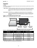
INDICATOR
LIGHT
INDICATOR
LIGHT
L2
L1
TRANSFORMER
24V
120V
INDICATOR
LIGHT
IGNITION
MODULE
IGN/120
L1
IGN/240
L2
IGN/FS
PS
TH
24V
VAL
GND
C
G
T'STAT
TERMINAL*
LOW FIRE
HIGH FIRE
P.S.
5
HL2-DS/HL3/AG2 SERIES
LLWT106
*W/YELLOW CORD
W G
BK
25
HL2-DS
Series
Electrical Requirements and Wiring Diagrams
All field installed wiring to the tube heater must be must be done in accordance with the national,
state, provincial, local codes, and to the guidelines in this manual. In the United States, refer to the
most current revisions to the Electrical Code ANSI/NFPA 70. The unit must be electrically grounded
according to these codes. Line polarity must be observed when making field connections.
Internal Wiring Diagram
Before wiring this appliance, check the existing wiring; replace if necessary. If any of the original wire
supplied with the appliance must be replaced, it must be replaced with copper wiring material having
a rating of at least 300 V, 105°C.
Figure 3.15
•
Internal Wiring Diagram
WARNING
!
Shock hazard. Disconnect power supply before making wiring connections to prevent
electrical shock and equipment damage.
Any original factory wiring that requires replacement must be replaced with wiring
material having a temperature rating of at least 105°C minimum voltage.
3.0
Installation
•
Electrical Requirements and Wiring Diagram
•
Internal Wiring Diagram
Содержание HL2-DS Series
Страница 39: ...39 HL2 DS Series 7 0 Maintenance Notes Notes ...


