http://echoring.com
Revision: 1
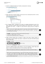
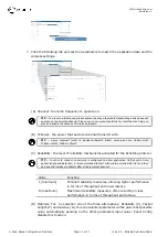
3. Click the ”Configure Deployment” button underneath to continue.
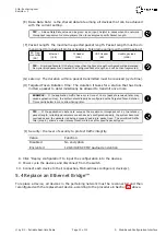
4. Please determine the MAC address of the device to be connected and enter it to the
right of the device’s (Node) IP address.
5. The “Capacity Factor” configures the number of available transmission slots of the
device, allowing for greater data rate (throughput), asymmetric traffic, or synchronicity
optimization per device - in relation to overall network capacity (which is configured
later).
TIP
— To derive the required capacity factor for each device, simply analyze the traffic and
corresponding data rate each device transmits, in relation to all devices in network. Then portion
out capacity factors accordingly.
EXAMPLE
— 3 devices have a combined network data rate of 200 kb/s,
1 device has 2 capacity factors = 100 kb/s,
2 devices have 1 capacity factor each = 50 kb/s each
i
6. Apply prioritized traffic filter (if needed) in bottom field under “Priority Traffic” by
entering the prioritized data’s “byte index”, counted from the start of the MAC header,
and its “Byte value”.
EXAMPLE
— Profinet:
EtherType
MAC header
0x88
0x92
←
Byte Values
|
−−−−−−−−−−−−−−−−−−−−−−→
|
−−−−→
|
Byte index 12
13
i
To filter for additional/other packet aspects, such as IP addresses, packet flags, QoS
fields or similar, add additional entries to the prioritized traffic filter.
TIP
— Filter entries work as AND function, meaning data to be prioritized must match all entries.
TIP
— Data to be transmitted is buffered in a queue and transmitted when its device’s transmission
slot arrives. If the application has multiple traffic types - such as critical control/safety packets or
best-effort packets - they can be prioritized via a filter. Packets matching the filter will be buffered
in an alternate queue and sent prior to packets in the main queue. If no prioritized traffic is set, all
data is treated as equally critical.
© by R3 – Reliable Real-time Radio
Page 9 of 11
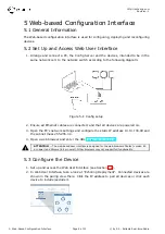
5. Web-based Configuration Interface


