background image


Copyright Qvis ®. All documentation rights reserved. 

12 

You can refer to the following sheet and Figure 1-8 for alarm input and output information: 


Parameter 
 

Grounding Alarm   


Ground line 

1, 2, 3, 4. 

Alarm input 1 to alarm input 4. It becomes valid in low voltage. 

NO C 

A group of normal open activation outputs. 

Rx,TX 

This  is  the  RS232  port  to  connect  to  the  COM  (debug),  keyboard 
port  and  transparent  port  (transfer  COM  input  and  output  via  the 
network).  

A/B 

RS485 communication port. They are used to control devices such 
as PTZ. Please parallel connect 120

T

Ω between A/B cables if there 

are too many PTZ decoders.


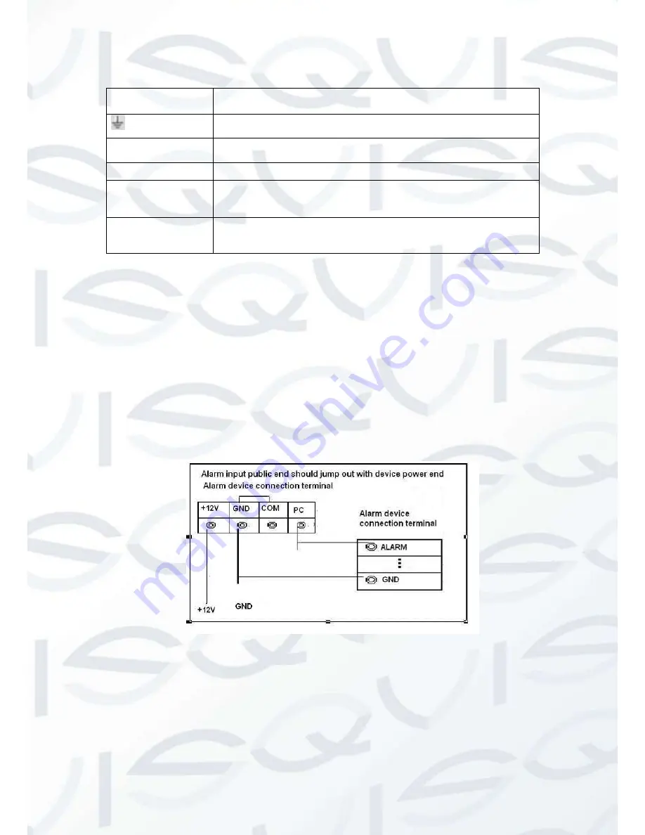
1.8.2  Alarm Input Port  

Please refer to the following points for more information: 


4-channel alarm input. Normal open or Normal close type. 


Please parallel connect COM end and GND end of the alarm detector (Provide external 

power to the alarm detector). 


Please parallel connect the Ground of the compact DVR and the ground of the alarm 

detector. 


Please connect the NC port of the alarm sensor to the compact DVR alarm input (ALARM) 


Use the same ground with that of compact DVR if you use external power to the alarm 

device. 


Figure 1-9 

1.8.3  Alarm Output Port 


1-channel relay alarm output (NO contact). Provide external power to external alarm device.  


To avoid overloading, please read relay parameters sheet in the 

User’s Manual

 carefully.  


RS485 A/B cable is for the A/B cable of the PTZ decoder.  


Содержание APOLLOC4-500

Страница 1: ...Copyright Qvis All documentation rights reserved 1 APOLLOC4 500 APOLLOC8 500 4 8 Channel Full Realtime D1 Compact Digital Video Recorder Quick Start Guide V 1 0 0 11 2013...

Страница 2: ...Copyright Qvis All documentation rights reserved 2...

Страница 3: ...Input Port 12 1 8 3 Alarm Output Port 12 2 Overview of Navigation and Controls 13 2 1 Login Logout Main Menu 13 2 1 1 Login 13 2 1 2 Main Menu 13 2 1 3 Shutdown 14 2 1 4 Auto Resume after Power Failu...

Страница 4: ...r system Please open the accessory bag to check the items one by one in accordance with the list below Contact your local retailer ASAP if something is missing or damaged in the bag Here you can find...

Страница 5: ...rs needed All the examination and repair work should be done by the qualified service engineers We are not liable for any problems caused by unauthorized modifications or attempted repair 5 Environmen...

Страница 6: ...the compact DVR Note Remote control is not a standard accessory and it is not included in the accessory bag 1 2 Device Installation The series product supports two installation modes desktop wall moun...

Страница 7: ...2 1 4 HDD Installation This series 10 2 inch compact DVR has only one 2 5 inch SATA HDD Please follow the instructions below to install the HDD 1 Turn the screw of the HDD cover and then remove the H...

Страница 8: ...Copyright Qvis All documentation rights reserved 8 3 Fix the HDD 4 Install the HDD cover 5 Secure the screw of the HDD cover Now the installation completed...

Страница 9: ...ed 9 1 5 Dimensions You can refer to the following two figures for dimension information see Figure 1 3 Figure 1 4 Figure 1 3 Figure 1 4 1 6 Front Panel Side Panel and Rear Panel The front panel and s...

Страница 10: ...D data 3 Power indication light The light is on when the device is connected to the power 4 5 USB port 6 On off button When the device is off press it for a long time to boot up the device When the de...

Страница 11: ...ure 1 7 for connection sample The following diagram is based on the 8 channel series product Figure 1 7 1 8 Alarm Input and Output Connection There are two alarm input types for you to select normal o...

Страница 12: ...coders T 1 8 2 Alarm Input Port Please refer to the following points for more information 4 channel alarm input Normal open or Normal close type Please parallel connect COM end and GND end of the alar...

Страница 13: ...me default Password default hidden user You can use USB mouse front panel remote control not included in the accessory bag or keyboard to input About input method Click to switch between numeral Engli...

Страница 14: ...ecommended In the main menu click shutdown button you can see an interface is shown as below See Figure 2 3 Figure 2 3 There are several options for you See Figure 2 4 Please select the shutdown item...

Страница 15: ...ement the following operations Please make sure the HDDs have been properly installed After the system has booted up it is in default 24 hour regular mode You can set record type and time in schedule...

Страница 16: ...rd when the MD and alarm occurs system will not record neither motion detect occurs nor the alarm occurs Figure 2 5 2 4 Manual Record Note Please make sure you have the record operation right and you...

Страница 17: ...e 1 channel resolution is D1 PAL 25f s NTSC 30f s CIF QCIF The rest seven channels channel 2 to channel 7 support D1 PAL 6f s NTSC 7f s CIF QCIF Bit rate type system supports two types CBR and VBR In...

Страница 18: ...Figure 2 8 Figure 2 8 2 5 1 2 Activation Snapshot Please follow the steps listed below to enable the activation snapshot function After you enabled this function system can snapshot when the correspo...

Страница 19: ...d then click save button See Figure 2 10 Please refer to the User s Manual included in the resource CD for detailed information Please boot up the corresponding FTP server Please enable schedule snaps...

Страница 20: ...Previous channel 13 Search 14 Backup 15 Clip 2 6 1 Basic Operation 2 6 1 1 Playback Operation There are various search modes video type channel number or time The system can max display 128 files in o...

Страница 21: ...tion and then left click mouse to realize digital zoom You can right click mouse to exit 2 6 1 6 File backup and clip System supports backup operation during search You can draw a before file name mul...

Страница 22: ...ay button again system goes to pause mode When system is in backward play or frame by frame playback mode you can click play button to go to normal playback Manual playback frame by frame Click pause...

Страница 23: ...s interface due to various protocols Please make sure the speed domes A B cables are properly connected to the A B ports of compact DVR You have properly set PTZ information Please switch camera moni...

Страница 24: ...ation In one window display mode right click mouse click Fn Button in the front panel or click Fn key in the remote control The interface is shown as in Figure 2 15 Figure 2 15 Click Pan Tilt Zoom the...

Страница 25: ...g key See Figure 2 18 Please note this function needs protocol supported and can only be operated by mouse Click this key system goes back to the single screen mode Drag the mouse in the screen to adj...

Страница 26: ...un install the web controls please run uninstall webrec2 0 bat to auto delete the control or you can go to C Program Files webrec to delete Single folder 3 2 Login Open Internet Explorer and input com...

Страница 27: ...logged in you can see the main window See Figure 3 2 Click the channel name on the left side you can view the real time video Figure 3 2 Note Slight difference may be found in user interface All the...

Страница 28: ...tion rights reserved 28 For more information about our DVRs and available cameras accessories please visit our website www adata co uk Alternatively scan this QR code with your smart phone to be direc...

Отзывы: