background image

Industrial Series

Quincy Compressor

50263-106, October 2004

11

3501 Wisman Lane, Quincy IL - 62305-3116

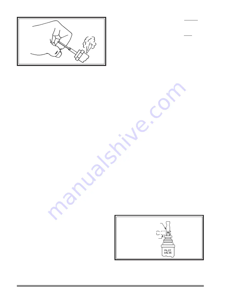
Manually Draining An Air Tank:

Tank(s) subjected to freezing temperatures may con-
tain ice. Store the compressor in a heated area before
attempting to drain moisture from the tank(s).

Step 1)

Disconnect and lockout the compressor from
the power source (electric models) or discon-
nect the spark plug wire from the spark plug
(gas engine models).

Step 2)

Reduce the air pressure in the tank to 30
PSIG by pulling the pressure relief valve ring

(see Fig. 11).

Step 3)

Position yourself so that the moisture and air
to be expelled can not cause you harm.

Step 4)

Open the drain valve and allow the moisture
and air mixture to drain from the tank.

Step 5)

Once the moisture has been completely
drained, close the drain valve.

PRE-STARTING
CHECKLIST

WARNING !

Failure to perform the PRE-STARTING CHECKLIST
may result in mechanical failure, property damage,
serious injury or even death.

Steps 1 through 5 should be performed prior to
operating the unit. If any condition of the checklist is
not satisfied, make the necessary adjustments or
corrections before starting the compressor.

For gas engine start-up procedures, refer to the

gas engine owner’s manual.

WARNING !

Never assume a compressor is safe to work on just
because it is not operating. It could restart at any
time. Follow all safety precautions outlined in MAIN-
TENANCE.

Step 1)

Basic compressors are shipped without lu-
bricant in the crankcase. Add lubricant per
specifications.

 (Refer to Lubrication).

Tank mounted units are shipped with break-
in lubricant in the crankcase. Check for proper
lubricant level. 

(Refer to Lubrication.)

Step 2)

Make sure all pressure relief valves are cor-
rectly installed. 

(Refer to SYSTEM COMPO-

NENTS)

Step 3)

Be sure all guards are in place and securely
mounted.

 (Refer to SYSTEM COMPO-

NENTS)

Step 4)

On electric motor driven units, check fuses,
circuit breakers, and overload relays for
proper sizes.

Step 5)

Open the tank drain valve in the bottom of
the tank.

STARTING & STOPPING
THE COMPRESSOR

Constant Run Models

Step 1)

Flip the toggle on the pilot valve to the
“MANUAL UNLOAD” position 

(see Fig. 12)

.

Step 2)

Start the compressor by plugging the power
cord into a properly grounded and rated
power source (electric models) or by starting
the gas engine (refer to gas engine owner’s
manual for start-up procedures).

Step 3)

Allow the compressor to run for a few min-
utes.

Step 4)

Flip the toggle on the pilot valve to the “RUN”
position. The compressor will start to deliver
compressed air to the tank.

Step 5)

Watch and listen for excessive vibration and
unusal noises. If either exist, stop the com-
pressor and refer to 

TROUBLESHOOT-

ING.

Fig. 11 Checking Pressure Relief Valves

& Relieving System Pressure

Pix 1160

Fig. 12 Constant Run Starting

Toggle in

"MANUAL UNLOAD"

Position

Toggle in

"RUN"

Position

Содержание QTS Series

Страница 1: ...entirety and understood prior to installation by all personnel who install operate and or maintain this product Manual No 50263 106 October 2004 Edition Instruction Manual QTS QTS QTS QTS QTS Industr...

Страница 2: ...received a completed warranty registration card within thirty 30 days of your purchase of this compressor or at the time service is requested you must be prepared to provide proof of purchase in the f...

Страница 3: ...t motor only DANGER Under no circumstances should a compressor be used in an area where toxic volatile or corrosive agents are used or stored near the compressor This instruction manual and any instru...

Страница 4: ...iring Schematic for 120 VAC Single Phase 1 Thru 5 h p Stationary Units WP 1753A Fig 2 Wiring Schematic for 240 VAC Single Phase 1 Thru 5 h p Portable Units WP 1753C Fig 4 Wiring Schematic for 240 VAC...

Страница 5: ...16 Fig 5 Four Cylinder Single Stage 3 Phase Units With 1750 RPM Motor Only Wiring Schematic WP1744A Magnetic Starter Contactor Overload Relay Connect incoming power lines at screw terminals L1 L2 L3 C...

Страница 6: ...nections at screw terminals L1 L2 Fig 6 Four Cylinder Single Stage Single Phase Units With 1750 RPM Motor Only Wiring Schematic WP1744B Magnetic Starter Contactor Overload Relay Connect incoming power...

Страница 7: ...pacitor Start Capacitor Run 3450 RPM Motor Only Wiring Schematic WP1753 Install incoming power line connections at screw terminals L1 L2 Pressure Switch Connect incoming power line at this screw termi...

Страница 8: ...L 62305 3116 Fig 8 Single Phase MDR Pressure Switch Overload Relay 1750 RPM Motor Connection Diagram Rated 22 30 Amps Connect incoming power lines at screw terminals L1 L2 Pressure Switch CAUTION Veri...

Страница 9: ...a problem Do not operate the compressor until the source has been identified and corrected by a qualified techni cian Electrical Information The installation electric motor wiring and all elec trical...

Страница 10: ...tment instructions from the manufacturer includedintheenvelopeshippedwith the compressor unit Pressure Relief Valves Pressure relief valves aid in preventing system fail ures by relieving system press...

Страница 11: ...other contaminants Compressed Air Discharge System All parts of the discharge piping should fit so as not to create any stress between the piping and connec tions WARNING Discharge piping can exceed 3...

Страница 12: ...ing It could restart at any time Follow all safety precautions outlined in MAIN TENANCE Step 1 Basic compressors are shipped without lu bricant in the crankcase Add lubricant per specifications Refer...

Страница 13: ...dicatethepresenceofcondensedliquids Refer to TROUBLESHOOTING Drain the air tank drop legs and moisture traps in air distribution system Tank s subjected to freezing temperatures may contain ice Store...

Страница 14: ...distributor in several container sizes Refer to the parts manual for part numbers A non detergent SAE 10W SAE 20W or SAE 30 weight lubricant may be used in your compressor Refer to the chart below to...

Страница 15: ...uns parallel to the straightedge Use a wheel puller to move the motor pulley on the shaft Properly adjusted a 3 pound pressure applied to the belt between the motor pulley and the compres sor flywheel...

Страница 16: ...aximum pressure will void the warranty and may cause personal injury Step 3 Turn clockwise to increase unload pres sure turn counterclockwise to decrease unloadpressure Holdpositionwithwrench and proc...

Страница 17: ...Industrial Series Quincy Compressor 50263 106 October 2004 16 3501 Wisman Lane Quincy IL 62305 3116 DECAL LOCATIONS...

Страница 18: ...Industrial Series Quincy Compressor 50263 106 October 2004 17 3501 Wisman Lane Quincy IL 62305 3116 TYPICAL DECAL LOCATIONS FOR VERTICAL UNITS model QT 5 vertical unit shown...

Страница 19: ...used 3 Replace check valve or unloader 4 Check with voltmeter 5 Replace with correctly sized motor 6 Check for proper size fuse 7 Replace motor 8 Change power cord voltage of motor to match voltage o...

Страница 20: ...fer to Belt Alignment Adjustment 11 Replace motor 12 Move the compressor to a well ventilated area 13 Change power cord voltage of motor to match voltage of power source PROBLEM CAUSES CORRECTION 1 Re...

Страница 21: ...ed up to high enough pressure faulty regulator 11 Insufficient pressure at tool or accessory 1 Contact qualified electrician 1 Reversed wiring polarity 10 Compressor runs backwards 1 Change lubricant...

Страница 22: ...der head cooling fins 3 Unit is undersized for applica tion 4 Insufficient lubrication 5 Compressor runs backwards 6 One or more head valves failing to seat properly 7 Damaged cylinder head gasket 8 R...

Страница 23: ...n thirty 30 days after receipt of notification of readiness for shipment Claims for shortages will be deemed to have been waived if not made in writing with ten 10 days after the receipt of the materi...

Страница 24: ...he instruction manual provided with Quincy Compressor products as well as any instructions supplied by manufacturers of supporting equipment should be read and understood prior to performing maintenan...

Страница 25: ......

Страница 26: ...Systems ocating Systems ocating Systems ocating Systems 217 222 7700 Air Master Air Master Air Master Air Master Air Master 217 277 0270 E mail E mail E mail E mail E mail info quincycompressor com We...

Отзывы: